Post pics of your builds....
Jan 19, 2009 at 5:07 AM Post #4,186 of 9,811
Scy, awesome build! Very, very nice.

Beefy, you will certainly be missed in the DIY world, but congrats on your new job.

Pavel, nice work. Its a very busy board, and it looks like you did a good job of making this modification, especially since that wire looks a bit thick and cumbersome for this. Guess this is one of those times that 1600x1200 isnt even close to high enough resolution to tell what is going on.
 
Jan 19, 2009 at 11:53 AM Post #4,188 of 9,811
Quote:

Originally Posted by cobaltmute /img/forum/go_quote.gif
Beefy, congrats and you should take your station along with you for the times when you get snowed in.


Fair point...... but from all reports, Halifax has great pubs. It will be a tough decision!
wink.gif
 
Jan 19, 2009 at 12:01 PM Post #4,189 of 9,811
Wow...i just ran trough this thread and I'm simply amazed by talent (and will power) of people here. This is gonna be awesome read. Just wanted to say, one of the best threads I've found here and i hope to join with some projects myself one day.
 
Jan 19, 2009 at 12:59 PM Post #4,190 of 9,811
Quote:

Originally Posted by Beefy /img/forum/go_quote.gif
Fair point...... but from all reports, Halifax has great pubs. It will be a tough decision!
wink.gif


True, but you have to get out the door to get to them.
tongue.gif
 
Jan 19, 2009 at 7:54 PM Post #4,192 of 9,811
Quote:

Originally Posted by FallenAngel /img/forum/go_quote.gif
I needed to use a Creative X-Fi card (as they are the only ones that pass 3D-CMSS through S/PDIF). Now I didn't really like the weird and overdone S/PDIF implementation of their cards so with the wonderful help of Colin Toole (cetoole on the forum), I tapped the S/PDIF output straight off the X-Fi card (before it gets multiplexed and messed around with), installed a pulse transformer, 75 Ohm wiring and a BNC jack output that now runs to my DAC. Needless to say, it works wonderfully and passes all the gaming effects.


Which flavor of X-Fi card did you use? Do you think you could go into a bit more detail on the modification? Parts used, etc...
 
Jan 19, 2009 at 8:24 PM Post #4,193 of 9,811
Quote:

Originally Posted by patton713MW /img/forum/go_quote.gif
Which flavor of X-Fi card did you use? Do you think you could go into a bit more detail on the modification? Parts used, etc...


X-Fi XtremeMusic (retail, not OEM, make sure! If it doesn't come with the retail box, don't buy it! I cannot stress this enough).

Newava S22083 pulse transformer, 0.1uF cap to ground, 300R inline with S/PDIF signal, 97.6R across output of transformer.

The harder part (if you already had Colin recommend you the parts and how they work together of course
tongue.gif
) was finding where the S/PDIF signal comes from and finding where to tap it. It ended up being the 74F125D buffer, before the multiplexer. As you might can see from the photo, pin 4 was used for ground and pin 6 for S/PDIF output.
 
Jan 19, 2009 at 10:31 PM Post #4,194 of 9,811
Quote:

Originally Posted by Beefy /img/forum/go_quote.gif
Today is a day of mixed emotions - the end of the first chapter of my DIY story.


Look forward to chapter two.

Quote:

I'm moving to Halifax, Canada for work in a couple of months ...


So if your in North America that means we could get together for a meet!!!
atsmile.gif


Quote:

A huge thanks to everyone who provided help and inspiration. It has been a blast!
smily_headphones1.gif


If you only knew how many times I picked up a tip from reading your posts, not to mention many many laughs.
icon10.gif

I certainly hope to see you online from time to time.
Wouldn't be the same without ya.
 
Jan 20, 2009 at 10:37 PM Post #4,198 of 9,811
Quote:

Originally Posted by adamus /img/forum/go_quote.gif
7 minutes work produces... an input selector with rotarty encoder, the start of a preamp.


Looks great adamaus! Is it a kit? if so.... where did you get it?
 
Jan 21, 2009 at 6:58 AM Post #4,199 of 9,811
Its a kit, diyzone, or ebay, several of the chinese diy shops stock something similar.

its just a rotary switch with a few diodes to open one relay at a time.

the LEDs arent moutning yet, i will be running them on the front pannel.
 
Jan 22, 2009 at 6:46 AM Post #4,200 of 9,811
these are just work-in-progress photos but the concept seems to work and so I wanted to share it before the project is fully done.

the idea is to have a pimeta board be the center of a home preamp. that's not all that unusual but what's a bit different is that I've 'stolen' the 3rd 'ground channel' and used it for a bass channel! or rather a subwoofer amp mono channel.

I was willing to let go of the 'high end' virtual ground buffer channel and use that set of opamps/buffers for driving my subwoofer. all I had to do was rewire the pimeta board a bit and instead of the ground channel taking its input from 'ground', I let the input of that single mono channel come from a summed (left+right) that came from 2 resistors from L and R. since I wanted the bass channel to be based on the main 2 L,R channels, the input to the bass channel comes from the output of the L,R and so when you vary the volume on the L,R pair, the input to the bass channel also goes louder, as you'd want.

I have a volume pot on that point, between the L,R outputs and the bass channel input. that lets me 'trim' the bass amount as you would normally do on a home theater stereo or a preamp with a bass level control.

pics:

3217528350_6441cd2ac9_o.jpg


3217528712_4e7bea78c0_o.jpg


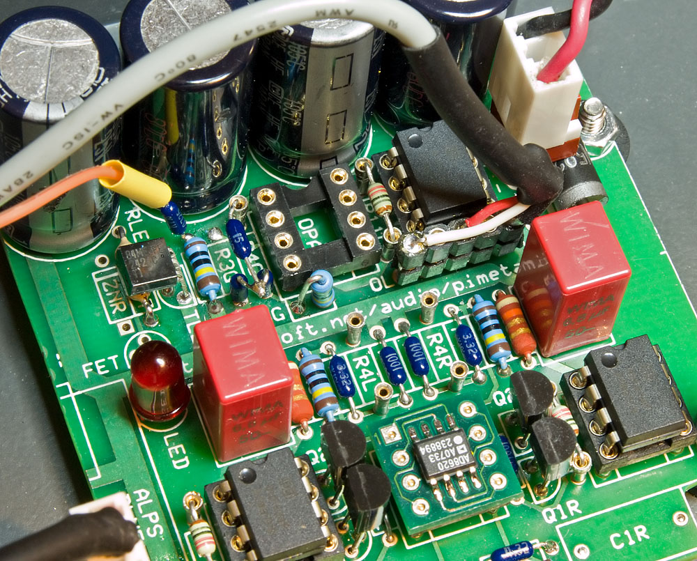
first photo shows the area of the pimeta board that needed modifying. in the center where its marked C6G is where a new resistor (1M) goes which is the feedback loop, as the other 2 L,R stages have. there's a 15k R on its side (marked 15) and that's similar to the R4 gain setting resistor in the L,R channels.

a leg on the R3G spot is lifted and similarly one is lifted on R1G. a new R is added on its end in the R4G spot and a new junction is soldered 'on top' in place.

all this is to replicate as closely as possible the same topology of the circuit as the L and R has. the ground channel was always a little different (unity gain, etc) but I wanted to convert it to being the same as L and R so that my bass channel was as closely matched as possible.

3217563190_6842e81b89_o.jpg


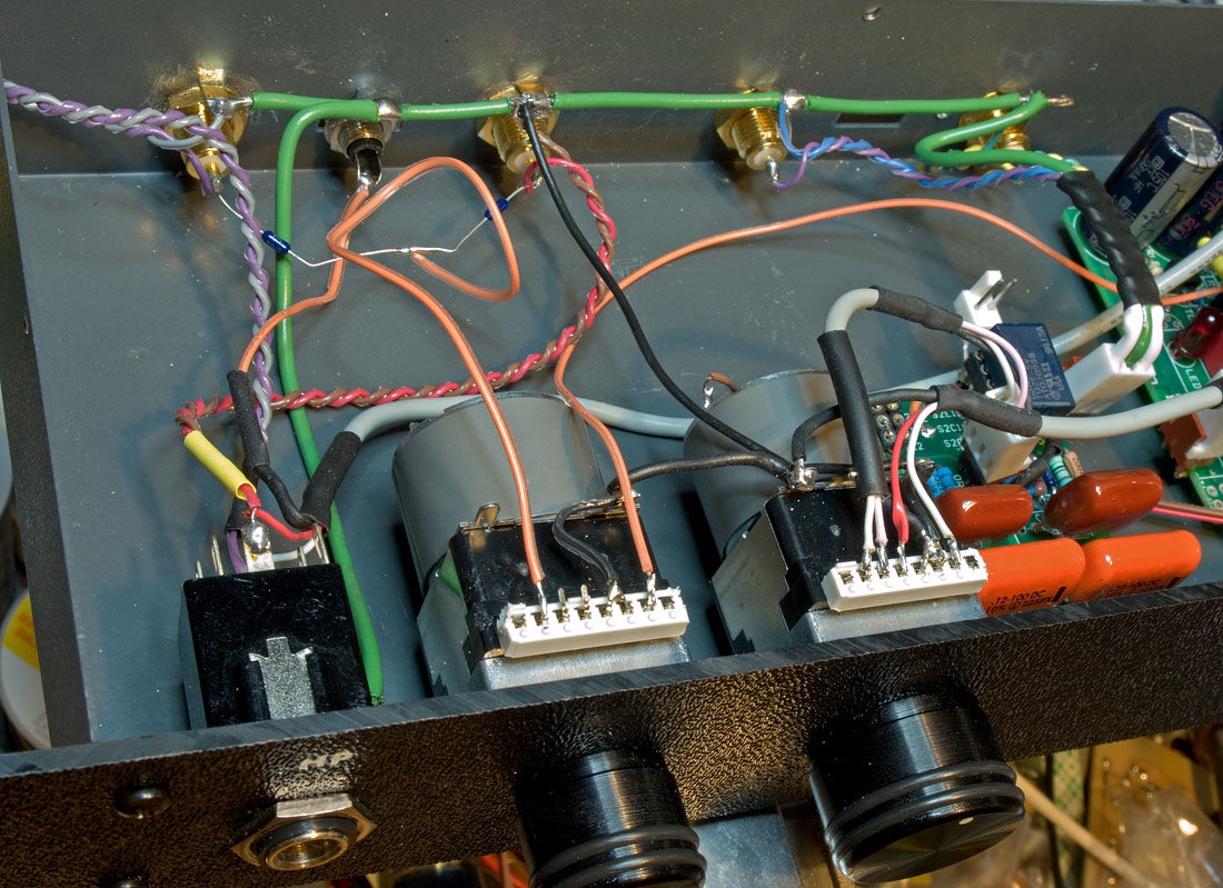
the orange wire going into and out of the pot on the far left is the bass wire. you can see the 2 temporarily mounted (!) resistors on the 2 gold rca output jacks that form a summing network that just combines both channels into a mono single channel, ready to send into the bass-volume control pot. the long thick green wire is a ground bus.
 

Users who are viewing this thread

Back
Top