Post pics of your builds....
Dec 2, 2007 at 2:23 PM Post #2,701 of 9,811
My SOHA...

S4200047-klein.jpg


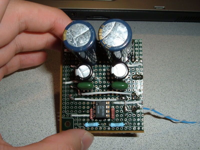
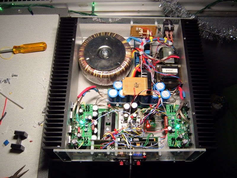
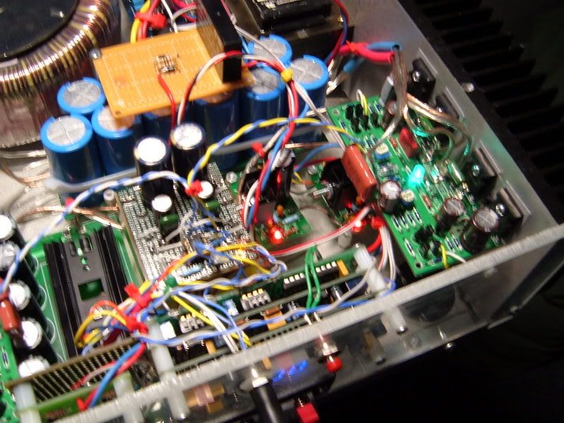
Pretty much standard. Used Xicon resistors, Xicon caps for the power section and some Muse KZ and Panasonic FMs here and there. Opamp is an AD8512, tube... uh, I don't know, I used the one Jeff sent me
biggrin.gif


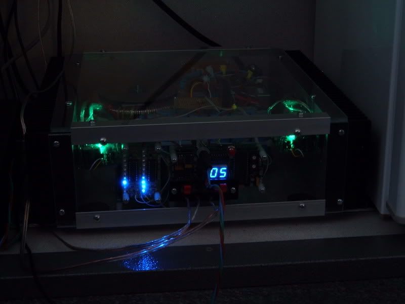
Now looking forward to building some JISBOS... and of course to case it up!
 
Dec 3, 2007 at 12:44 AM Post #2,703 of 9,811
How do you guys post pics larger that 19Kb? Do you have to be a paid member or something? I want to post pics of my newly finished CKKIII.
confused.gif


Thnaks
James
 
Dec 3, 2007 at 1:23 AM Post #2,704 of 9,811
just host them through photobucket (free) and then use the "insert photo" feature to post the direct URLs to the photobucket hosted images when posting your replies on head-fi
 
Dec 3, 2007 at 1:52 AM Post #2,705 of 9,811
HPIM0966.JPG


el_matto Thanks... I got it to work from my picassa web album. Very nice, just sold these BTW

james
 
Dec 3, 2007 at 2:56 PM Post #2,706 of 9,811
My first effort in building headphone amplifiers...
This one is using the C3g, a tube that was exclusively built for the german post in the 60's. A few years back hardly nobody knew this tube, now it's been used here and there...

Quote:

This really is the ULTIMATE preamp tube. If you want one of the quietest and lowest microphonics tube on the planet, this is your chance.


Quote found on tubedepot...
biggrin.gif


The schematic is simple and straightforward and uses minimal parts. Resistors are Allen Bradley, Morganite, Holco and Kiwame, bypass capacitors are Oscon and output capacitors Siemens MKV. The psu uses a 5R4GYB (for looks...and rectification), two chokes and mkp caps throughout.


Dec 3, 2007 at 3:06 PM Post #2,707 of 9,811
biggrin.gif
Stixx that is a real beauty. Did you do all the case work too?
 
Dec 3, 2007 at 3:20 PM Post #2,708 of 9,811
@jamess71: err, sure...all from me...
biggrin.gif


Nah, just kidding!

The top plate is 8mm aluminum and was fabricated by a fellow colleague.
The woodwork is veneer over cherrywood and was done by my favourite carpenter (and I nearly went broke over that...
wink.gif
)

Thanks for the kind words!
 
Dec 4, 2007 at 5:21 AM Post #2,710 of 9,811
Continuation of work on my power amp.
DSCF6175.jpg

It's remote controlled (my roommate's universal remote controls it - remote controlled board is from Welborne Labs), has a soft-start circuit from 41Hz.com, 530VA toroidal transformer from Avel-Lindberg, a muting delay circuit I etched, and a VU meter (lowest two LEDs on left channel blew out on me...). The remote board is connected to a 5V power supply connected directly to the AC inlet. On power-on, the remote board sends 5V out to multiple relays to power on the amplifier and support circuitry.
DSCF6183.jpg

Buffer circuit I completed using perf-board. I did a PSpice analysis on the input sections of the VU meter and power amp, and it turns out that high-frequencies were attenuated (draws 65mA @ 20kHz) with the VU meter's input filters. I'm throwing in 2 buffer circuits (one for VU meter, one for power amplifier boards) based on the LM4562NA opamp (basically, the buffer circuits are CMoy amps (non-inverting amplifier) set to unity gain). The power supply for the buffer circuits will be two bridged TREADs from Tangent set to +/-12V DC. The primary buffer board has 2 solid-state relays that power the board on when the entire amp is powered on.
DSCF6180.jpg

Amplifier in action.
 
Dec 4, 2007 at 5:31 AM Post #2,711 of 9,811
@ polaris.
very nice, and very clever work there my friend.
 
Dec 6, 2007 at 4:17 PM Post #2,713 of 9,811
@ vixr, that looks wickedly cool man. kinda like an alien space ship
biggrin.gif
biggrin.gif
! is it a tube or SS amp?
 
Dec 7, 2007 at 6:29 AM Post #2,715 of 9,811
Sweet work, Vixr. I need to learn that sort of neatness with wiring and placement.

The power amplifier is finally finished, after today's addition of the buffer circuits. No more modifications are in line.
DSCF6218.jpg

DSCF6219.jpg

DSCF6220.jpg

Now, there are a total of 8 relays that power on the amplifier/output. The yellow LED indicates that the buffers are on, the green super-brights indicate that the amplifiers are on, and the red LEDs indicate stand-by (twin TREAD power supplies creating a +/-12V supply). High-frequencies are notably improved with the buffers in place. Two LM4562NAs are used as buffers. Yeah... there's no room left in this sucker.
 

Users who are viewing this thread

Back
Top