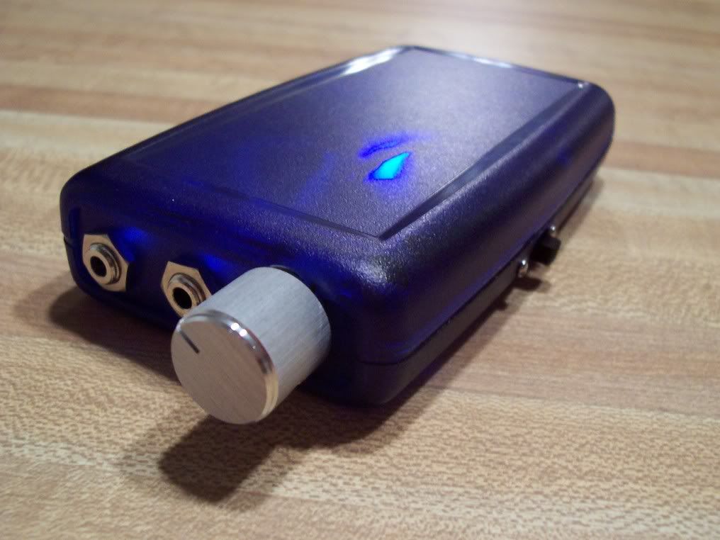
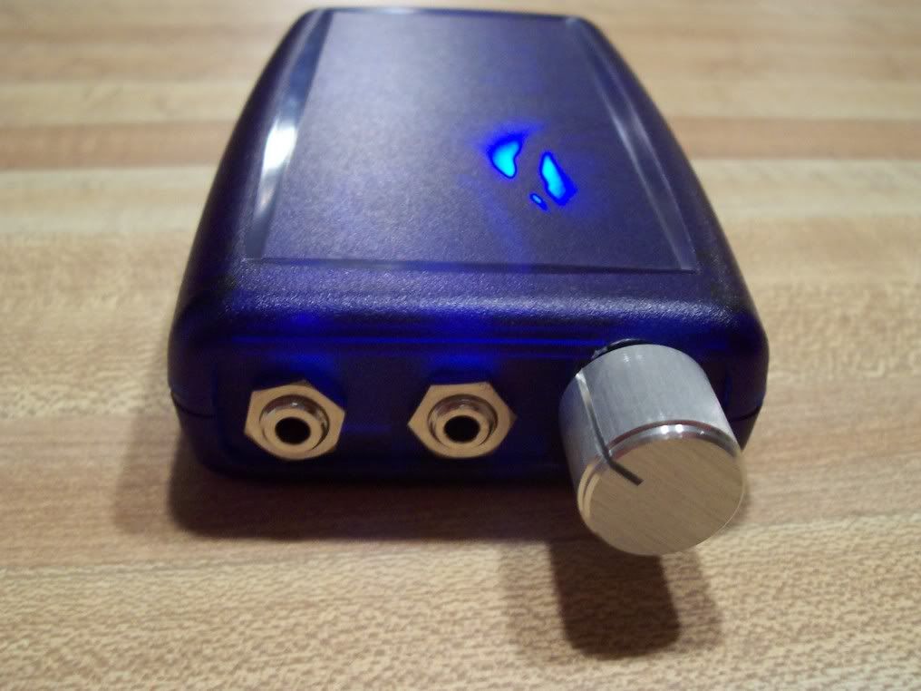
MINT w/ OPA2227
Clear Blue Serpac case
using 2x 9v batteries (Accu 270mah)
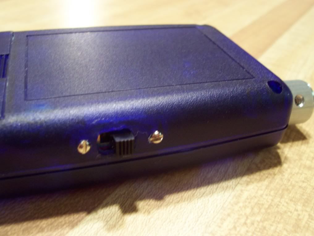
I had a time getting this amp cased up. The Serpac case is a tight fit with 2x 9volt batteries. I knew from the start that I wanted to mount the power switch on the side of the case. I also used a wide angle LED mounted directly to the PCB to give the inside of the case a little illumination. You can see the LED on in a couple of pics there. Looks cool in the dark.
The MINT itself was a really easy, quick build (except for case work
) but I don't really care for the sound that much. I assume this is due to the OP Amp I am using. Almost has a muddy sound with no real punch in the bottom end. I have not tested it with all my headphones yet. I will change the amp at a later date.
Anyone with experience in using pocket amps, where should i put my exterior components? Is a switch/knob/socket on the side fine, or should they all be on the ends?
Originally Posted by moeburn Where do you guys get your nice fancy aluminum knobs? I can't find any here, and I just ordered some but they're not as nice as these ones i'm seeing.
I finished my Multi-Hybrid. See here for the design: http://www.headphoneamp.co.kr/bbs/zb...sijosae&no=217
I designed my own PCB, used Panasonic FC caps bypassed with 100nF caps, 1% matched resistors, Alpha pot, IRF610s and a 6922 tube lit with a UV LED. I got it into the same hammond case my PIMETA fits into. It draws about 500mA at 24V. I used 20VA toroid and made my own regulator PCB based on the TREAD
I really like it and it is now the main amp I use. You can see more pics and get Eagle files on my page here: http://max8888.orcon.net.nz/hybrid.htm
Finished my first build, or at least the first one I'm keeping. I wasted my time with an LM386 amp and a plain-parts Cmoy. I designed this circuit myself, but it may as well be an A47 without the buffered rail splitter.
In use:
Oh sexy:
I forgot to calculate the pot in my measurements, so I was actually yelling "oh thank god it actually fits!"
Schematic: (power caps are 600uf 16v)
PCB:
Until I learn how to adapt the AD8620s, I'm using two OPA2111s as the next best thing. Output resistors are four 240ohm, they provided the best balance of volume loss vs clipping, and there is no clipping whatsoever and its still way too loud
I just got around to casing up my fourth M3. It's in a Lansing B2H08-V02B case that I was planning to use for just an M3 without a power supply. However, due to its height of 3 1/2", I found it would fit the Welborne PS-1 if I angled the transformer on a custom bracket and mounted the two PCBs at different heights so they could lap over a little. I was a bit concerned about EMI due to the cramped quarters, but it is as clean sounding as my other three, two of which have the PS in a separate case.
Now, since there is room, I'm considering larger heatsinks for the PS-1 since it is running a little hot with a 15v + 15v toroid.
My very first DIY amp. Just a plain CMoy with a blue LED to match the screen of my Dell DJ. Also I made a stand out of wood to hold both the DJ and the amp upright together. Next I just need to make some cables for this thing.
Originally Posted by nitsujH My very first DIY amp. Just a plain CMoy with a blue LED to match the screen of my Dell DJ. Also I made a stand out of wood to hold both the DJ and the amp upright together. Next I just need to make some cables for this thing.
Here are a few pics. As you can see the styling follows the tradition of my previous headphone amp builds. For more see my Millett page which also has extensive test results: http://www.amb.org/ti/audio/millett.html
This site uses cookies to help personalise content, tailor your experience and to keep you logged in if you register.
By continuing to use this site, you are consenting to our use of cookies.