Post pics of your builds....
Jul 30, 2005 at 2:55 AM Post #661 of 9,811
Quote:

Originally Posted by rjkdivin
Hey AMB....very nice looking build as usual. Is this physically the same size case as your M3 Prototype?

In listening trials, how does the 'ease of listening' compare to the M3 which I find wondefully non-fatigueing for extended listening periods.

Does the revised PCB incorporate the Diode modification to protect against polarity reversals discussed at the DIYForum.org ?


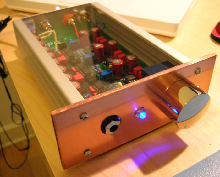
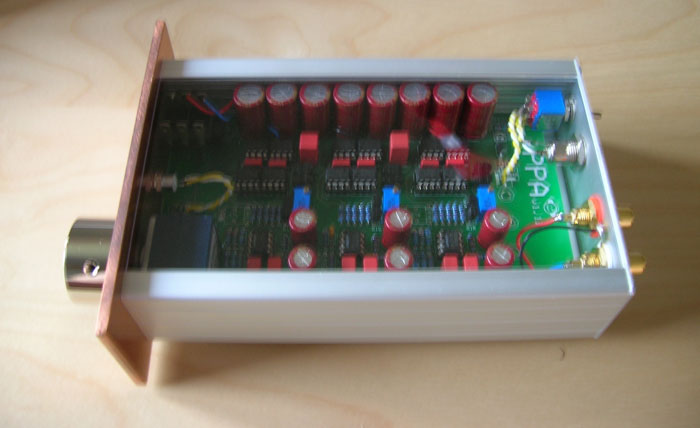
It looks smaller than the M3 proto. The revised PCB he used is the same one outlined at diyforum.org.


Nice work, Amb. The acrylic end panels are pimp.
 
Jul 30, 2005 at 5:08 AM Post #662 of 9,811
Quote:

Originally Posted by rjkdivin
Hey AMB....very nice looking build as usual. Is this physically the same size case as your M3 Prototype?


The Millett is smaller than my M³ proto. It is just a bit taller, but the width and depth are both smaller. Here is a pic of three of my amps together showing relative sizes (from left, clockwise: Modified SDS Labs amp, Millett Hybrid, M³).

headamp_trio.jpg


Quote:

In listening trials, how does the 'ease of listening' compare to the M3 which I find wondefully non-fatigueing for extended listening periods.


I haven't done much comparisons yet, should be interesting to do that. I'll be bringing all these amps to the San Jose meet so you could have a listen yourself.

Quote:

Does the revised PCB incorporate the Diode modification to protect against polarity reversals discussed at the DIYForum.org ?


No. The "revised" refer to the board design from n_maher and drewd rather than the original one from Pete Millett (which is sold via diycable.com). The circuit already has a form of reverse voltage protection. If you look at the schematic, there is a self-resetting fuse at the DC power input, and then there is an protection diode across the supply. This diode normally has no effect, but will conduct and cause a virtual short if the input DC is reversed in polarity or if the voltage is too high, and that will in turn cause the fuse to open.
 
Aug 7, 2005 at 6:39 PM Post #664 of 9,811
This is a Gilmore Dynamic that I finished other than the faceplate last spring. I am very pleased with the sound of this, driving a pair of AKG 401s predominately, and also some Grados. I think that it compares quite favorably with the Dynahi's that I have heard, as well as other amps (Raptor, etc.). Parts include a mix of Roederstein and PRP resistors, Nichicon Muse FX and Wima caps in the PSU and a TKD 2CP2511 pot. Jacks are Cardas; phone jack is a Neutrik ReAN. The PSU portion of the pic also shows the two PCBs I designed and etched to replace the packaged rectifiers used with 31DQ10 Shottky's. I'm still trying to decide on how I want to do the faceplate, so I just cut a piece of plexiglass to use for the time being. I am also going to add more inputs with selector switch, and an Amb relay board to mute the preamp output.

Gilmore_ft.JPG

Gilmore_back.JPG

Gilmore_amp.JPG

Gilmore_bd_close.JPG

Gilmore_PSU.JPG
 
Aug 7, 2005 at 7:45 PM Post #666 of 9,811
James281...that Millet + STEPS looks really sweet man...but uh...you kinda spelled 'Hybrid' wrong
frown.gif
 
Aug 7, 2005 at 7:48 PM Post #667 of 9,811
Very nice work James, I especially like the curved silk screening around the Headphone out. The clear tops look great.
wink.gif
 
Aug 7, 2005 at 8:21 PM Post #670 of 9,811
Quote:

Originally Posted by MisterX
At least he got the Millet part right.
biggrin.gif


I was going to say something about that the other day when I saw a pic of that amp
icon10.gif
atleast it is a funny typo... well atleast mullets are funny
 
Aug 8, 2005 at 5:56 PM Post #672 of 9,811
My first Chu Moy has finally got a smaller brother. The big brother is broudly in the first picture.
etysmile.gif


L%E4kerol%20ja%20Fishermans%20Friend.jpg

P%E4%E4lt%E4.jpg

Auki.jpg

Edest%E4.jpg


It's less than 60x60x20 millimeters (exluding the knob).

Unfortunately I made a small mistake with it. The input jack is too close to the knob (even though I did try to plan it). Luckily it's pretty easy to have another case.
 
Aug 9, 2005 at 2:17 AM Post #673 of 9,811
After solving my STEPS problem, I've done some heavy testing and casework, and here's the build at a soon to be complete stage.

The Millett board is the original board, with a few alterations in components. Caps are Blackgate standard series (Welborne was out of the Elna's, so I had to upgrade
eek.gif
), input jacks are Cardas cheapies (relatively), I have a neutrix headphone jack not wired up yet. The Linkwitz board uses Roederstein resistors and Wima caps. The case is an old Appletalk case I found walking home from work. I cut an aluminum bar for the jacks on the back.

Once I get it all put together, I'll post the finished pics.

Hey, anyone else with this build: do you need to run a wire from the Millett board to the case ground?

Cheers
 

Users who are viewing this thread

Back
Top