Post pics of your builds....
Oct 4, 2004 at 5:06 PM Post #46 of 9,811
I would like to give you guys 2 thumbs up!! Amazing, I might need to start doing this myself.

biggrin.gif
 
Oct 4, 2004 at 6:01 PM Post #47 of 9,811
Quote:

Im not sure if this has been done before....


tried but for some unknown reason no one took the bait.I then proceeded to cull pics from various threads and insert them into a sticky but that task became way too big of a deal and was also scrapped.

so here is "round ll" which i am making a sticky hping it becomes THE Head-Fi DIY Gallery for everything not cable related which has it's own sticky

Rickeraptor
cool.gif
 
Oct 6, 2004 at 2:32 AM Post #48 of 9,811
There are plenty of pics on my website (see my sig) but this one isn't on there yet.

This is a work in progress, a scratch-built Pete Millett hybrid. I've spent aboput 100 hours engineering the case machining and circuit board layout. My goal was to build the amp in the Olde School Way with Sprague Orange Drops, Atoms, Carbon Comp resistors and other old parts. I even thought about point-to-point but I'm not THAT crazy. The other goal was to capture the look of motorcycles built by Russell Mitchell's Exile Cycles (as seen on TV!) Just a raw, muscular, no bull**** piece of machinery that does it's job well and happens to look good at the same time.

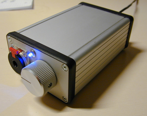
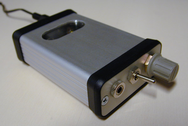
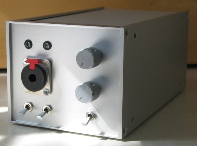
The case - a Hammond 1590N1 die-cast aluminum. Lots of machine time here. Finish is brushed aluminum covered with matte clear. Earwax - Hammond Cast Boxes Rawk!
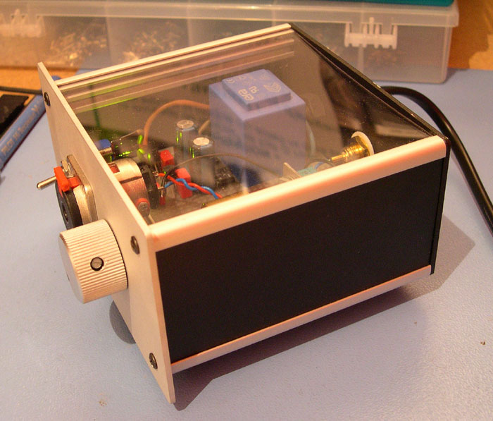
exile_amp_1.jpg


The Mock Up:
exile_amp_2.jpg

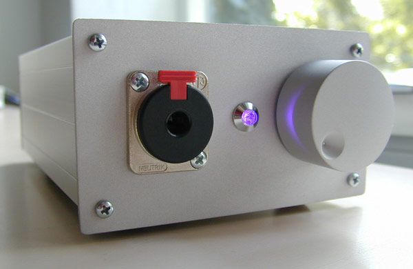
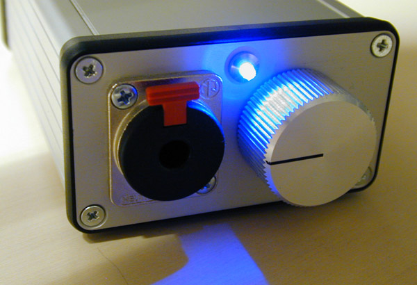
The big cap in the back has it's plastic coating cut off and lightly brushed with a scotchbrite pad. The knob is Davies, the jack is Switchcraft. The gloss black-painted covers over the buffers+heatsinks are drawn steel boxes from LMB (Mouser).
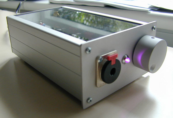
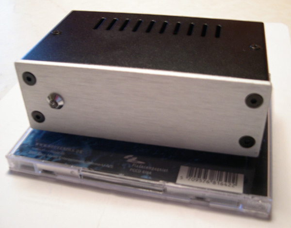
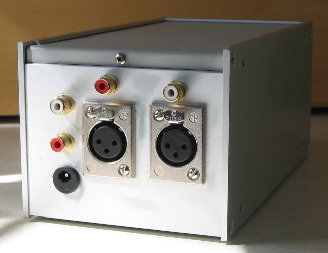
The Back Side:
exile_amp_3.jpg

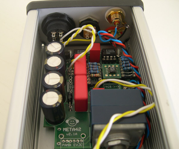
Power switch, power jack, Nickel-plated Swicthcraft jacks.
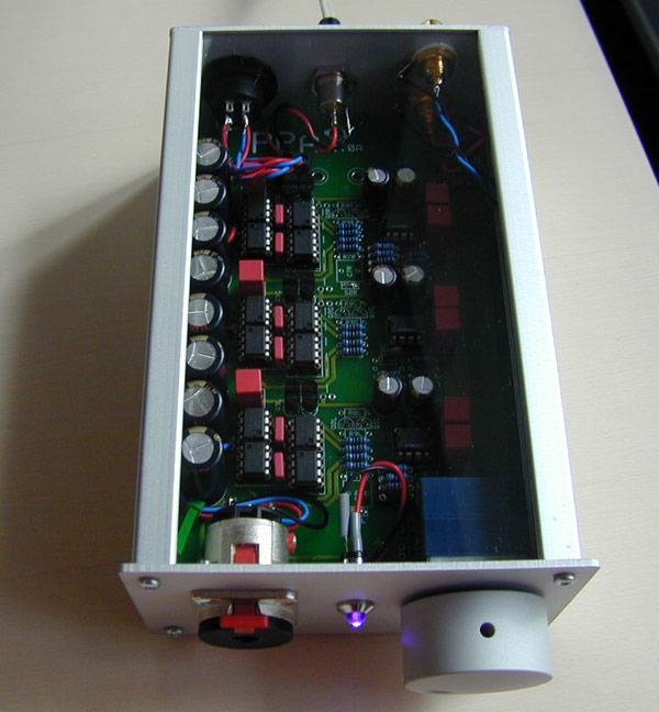
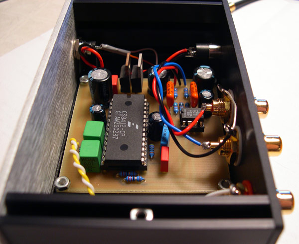
The ****:
exile_amp_4.jpg

The board is designed so that the tube sockets mount to the copper side. The side in this view will be populated with the above-mentioned Olde School parts. The board is held on by battery nuts and stainless-steel button-head screws.
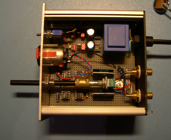
The Board:
exile_amp_5.jpg

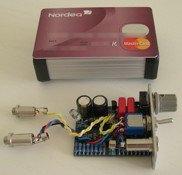
LOTS of layout time in this one (which is the second version - don't ask) and then three attempts at etching the board before I got Press-N-Peel Blue to work. Note the violet LED's in the middle of the sockets - should make 'em look like gas tubes!

The Parts:
exile_amp_6.jpg

Nothing fancy here!

Hope to populate the board this week - I'll let you know.

ok,
erix
 
Oct 6, 2004 at 10:14 PM Post #49 of 9,811
Well, these are all "old news" but since this thread is now a sticky I just have to post them again
wink.gif


My first PPA. v1.0 board, eurocard-sized case, laser-cut, bead-blasted aluminium front and rear panels, transparent top, OPA627 and a pink LED
smily_headphones1.gif

PPA-1a.jpg

PPA-1b.jpg

PPA-1e.jpg


My old META42: v2.1 board, standard Hammond case, AD8620 on browndog and one very bright blue LED
tongue.gif

META1b.jpg

META1d.jpg

META1g.jpg


My new "Disco"-MINT: Standard MINT with AD8620 in a Hammond 1455C801-enclosure. A flashing RGB-LED from www.lsdiodes.com means there's no mistaking when the amp is on
biggrin.gif

MINT1a.jpg

MINT1d.jpg

MINT1f.jpg

MINT1g.jpg

MINT1h.jpg


My very first headphoneamp: A buffered CMoy-design with on-board PSU (based on 78L09-regulators). The volume pot is an Alps RK09. The front and rear panels are laser-cut, bead blasted aluminium
smily_headphones1.gif

miniamp1b.jpg

miniamp1e.jpg


My Non-OS DAC with CS8412/TDA1543. Mainly built as an experiment to see if it worked. It did work and surprisingly well at that. The design is the NONOZ-II from www.fedde.tk and the PCB layout is my own. The LED on the front is a signal-lock indicator.
dac1c.jpg

dac1b.jpg


I have more pics and information on these on my homepage (see my sig)
smily_headphones1.gif


/U.
 
Oct 7, 2004 at 4:44 PM Post #52 of 9,811
SOme kinda oldies... not particularly impressive versus others in this thread, but my first builds.

Yet another MINT in a Hammond, this one is powered by a +/- 12V Elpac, and has additional filter caps mounted on a RatShack protoboard, along with a couple of 1n4002 diodes. All power connections are connectorized. Amp is housed in a J1201 1455 Hammond case (this size is only available from Allied).

Mint_front1.jpg


Mint_front2.jpg


Front view

Mint_rear1.jpg


Rear view, showing DIN connector for Elpac, mini and RCA inputs

MINT_inside.JPG


Inside, showing MINT board and additional cap board. 470uf Cerafines on MINT board, 2x1000uf Nichicon Muse KZ per rail. Connectors are HRS DF1B series from Digikey, allowing both inline and board header connections from the same connector series.

Amp uses BC resistors, Panasonic coupling caps, and is CRD-biased. 221 ohm R11s for the BW resistor.

A47_MINT.jpg


This shows a CMoy built per Tangent's tutorial on the left. It has been converted to an Apheared A47, and uses a Sijosae discrete rail splitter. Amp on the right is the MINT that my son built.
 
Oct 8, 2004 at 10:56 AM Post #56 of 9,811
Used a 3-AA battery compartment because 3 1.5v alkaline battery makes up 4.5V, just right for me 5V MuVo. No soldering, just lots and lots of taping.

Smaller form factor than its 4-AA cousin. The DC plug(which I ripped from a car cigarette lighter adapter) has interchangable plugs, which can be used with other appliances as well.
 
Oct 8, 2004 at 5:12 PM Post #58 of 9,811
Here's my latest PPA. Switchable between XLR and RCA inputs (with a balanced to single ended opamp-based converter circuit inside) and RCA passthrough. Adjustable/defeatable bass boost.

ppa_ken.jpg


ppa_ken_2.jpg
 

Users who are viewing this thread

Back
Top