Post pics of your builds....
Apr 23, 2009 at 10:22 AM Post #4,891 of 9,811
I'm in an introductory circuits class, and we got breadboards for our projects.

What's the first thing I do with mine?

Another cmoy using an opamp as power supply rail splitter (I think, it's on Tangent's web site).

17845789-1.jpg

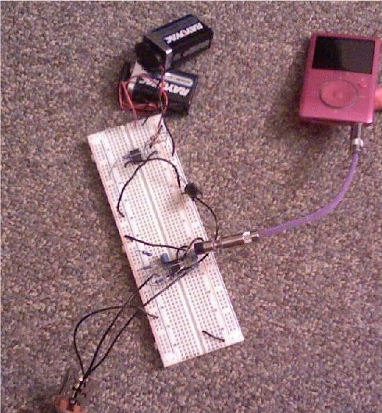
It sounded ok, nothing to write home about.

Then I tried the Very Simple Phono Stage, using the same power supply because I got lazy.

PICT1894.jpg

PICT1895.jpg

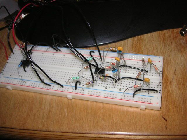
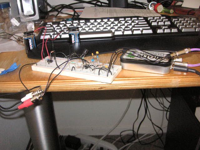
I can hear so much more from my vinyl now, a little too much more D:
I know the power supply is holding it back though.

This is the third Spring in a row I've posted in this thread. It's always in Spring. And it's always during the time I should be studying for finals lol.
Now, I need to get on that PROJECT.
 
Apr 23, 2009 at 5:33 PM Post #4,892 of 9,811
This is modified grado sr225..may be I should call it ps225?

 
Apr 23, 2009 at 8:32 PM Post #4,894 of 9,811
Quote:

Originally Posted by apatN /img/forum/go_quote.gif
^ Nice. Are those the cups from that guy from Spain?


I gave the drawings to machine shop guy and he made it for me.
 
Apr 23, 2009 at 9:24 PM Post #4,896 of 9,811
Quote:

Originally Posted by smeggy /img/forum/go_quote.gif
Nice!
Prices charged for those beauties?


Actually we worked together, he did main parts and I did easier parts like drilling.
His hourly rate is $35/hour and he spent good 4 hours to finish it, but I also put more than 10 hours of my time to do little touch up job. So, basically it is priceless LOL.
 
Apr 23, 2009 at 10:26 PM Post #4,898 of 9,811
Took me a while, sigh - started thinking about this last March when the HD 990 was announced - started building in January.

image1n.jpg


My first attempt at wood finishing - case is an old DVD player back in the day when composite was the only output option.

Feet are Vibrapod cones.

image2x.jpg


Balanced and unbalanced output, balanced XLR input for the H/K 2 x AD1955 output.

image3nzw.jpg


Four ECC83/12AX7 in a zero feedback differential circuit. Wiring point-to-point, protoboard there only for it to have a neater layout.

image4kxc.jpg


PSU end, custom potted transformer from Trafomatic.

image5zic.jpg


And another view.

image6j.jpg


And another view.

image7g.jpg


And the money shot.
 
Apr 24, 2009 at 6:40 AM Post #4,901 of 9,811
I got a little done on my M3 case tonight with the new mini mill:

3469674697_b81a1d2e48.jpg

3470487964_081de59854.jpg


I'm sort of happy with it. It's been a while since I've touched a mill so there are a couple minor issues that I can fix for next time.

Gotta set it up for the diagonal parts of the "M" and then figure out the Sigma for the PSU case. The sigma will basically be a sideways "M" though now that I think about it. There will be a little embellishment at the ends, but otherwise, it should be pretty straight forward as well.

I still haven't decided on any other slots. I might just put slots in the side or maybe the back panel. Or maybe even some sort of decorative slits on the front panel.
 
Apr 24, 2009 at 8:19 AM Post #4,902 of 9,811
Quote:

Originally Posted by zkool448 /img/forum/go_quote.gif
clever and clean!

nice touch with the wood and the money shot haha
beyersmile.png


You wouldn't believe the ugliness of the original plastic front. Since there are no knobs, I thought - why not - it should blend in with my other wood paneled components.

I might need to redo the front with a different type of wood. It was a first attempt anyway.

Quote:

Originally Posted by smeggy /img/forum/go_quote.gif
Nice plan and execution.. and that transfo look huge!


Thanks. Yeah, the transformer can is 5 inches in diameter, albeit the actual transformer is slightly smaller. It is 100VA, with 250V/0.1A + 50V/0.1A + 2 x 14V/2A secondaries.

The guys that built the transformer suggested the slightly larger potting canister for better cooling.
 
Apr 25, 2009 at 7:55 AM Post #4,903 of 9,811
A fellow Head-fier bribed me to assemble a starving student for him ( by offering me spare 19J6 tubes), he already had most of the parts but didn't have the time to assemble them, I just added a few touches of my own and we ended up with a very compact and nice sounding amp.

The bare circuit board
CIMG3550Medium.jpg


filling the board
CIMG3553Medium.jpg


Starting to take shape
CIMG3560Medium.jpg


Not much room
CIMG3573Medium.jpg


Finally in the carnage that I call a work bench a Starving Student comes to life
CIMG3580Medium.jpg

CIMG3581Medium.jpg

CIMG3586Medium.jpg


I think its cute and sounds great

Thanks for looking
cheers
FRED
 
Apr 25, 2009 at 8:09 AM Post #4,905 of 9,811
Thanks for the kind words, its very satisfying to make the boards

cheers
 

Users who are viewing this thread

Back
Top