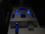
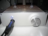
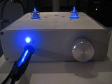
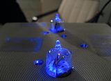
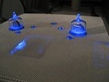
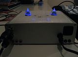
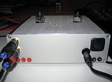
Post pics of your builds....
Oct 24, 2007 at 1:04 PM Post #2,641 of 9,811
Quote:

Originally Posted by Marzie /img/forum/go_quote.gif
...
On the DaftMoy, I didn't use a switch between the 2 inputs, i just wired them in series. Any disadvantages to doing it this way? ...


Don't you mean parallel? I hope you mean parallel, because I think with the inputs wired in parallel, as long as you only have one hooked up to a source, then the other shouldn't affect it, somebody correct me if I'm wrong.

Your multiple CMOYs make me want to make another (actually I've been meaning to), like a desk cmoy so I don't have to maneuver my fingers to get at the volume knob between the jacks, and so I don't have to worry about it falling off, and using a wall-wart so I don't have to worry about batteries, etc.
 
Oct 24, 2007 at 5:59 PM Post #2,642 of 9,811
Doh, yes I did mean in parallel.

Quote:

Originally Posted by kanamin /img/forum/go_quote.gif
Your multiple CMOYs make me want to make another (actually I've been meaning to), like a desk cmoy so I don't have to maneuver my fingers to get at the volume knob between the jacks, and so I don't have to worry about it falling off, and using a wall-wart so I don't have to worry about batteries, etc.


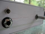
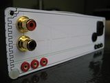
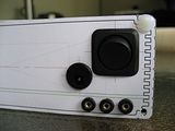
That is kind of where I am at now. I built the last one because I had the gain of the first 2 at 11 and that was too high for my ZVM. It gave me an excuse to throw in the extra inputs and outputs, so unfortunately, now it is almost too big to be easily portable (I just bring it to work in a bag) although I made the circuit with the portable player in mind... Next I was thinking more along the lines of a desk Pimeta, though. Then I could leave the third cmoy at work, have a nice desktop for at home, and I was thinking of rebuilding the DaftMoy circuit to have a lower gain (or maybe adjustable?) The case is pretty portable, and my attempt at being artistic (lol
tongue.gif
) shouldn't be doomed to stay at home. I am dreading taking out the rca jacks, as I have to desolder them to remove the board from the case. I have seen a few nice jacks that allow them to be unscrewed from the outside, maybe I will try some of those while I have board out.

On a side note, the case I used for the DaftMoy came with these nice rubber feet that hide the holes for the screws. Really keeps it stationary on the desk. A few gripes with the case though are the thick side walls, the 3.5mm jacks are just barely hanging onto the nuts (is that normal?), the split between the two halves of the case is practically right in the middle, so I decided to mount the board and components to the top half. Also, slot to pass the 9v clip through wasn't big enough for the heavy duty radioshack clips, so I had to file it to make it a little bigger.
 
Oct 25, 2007 at 12:14 PM Post #2,643 of 9,811
11 was too high for me too, but all I did was swap out two resistors to change it to 6...

I'm also currently thinking about a desk PIMETA, but am also considering a SOHA (gotta love the fact it comes in a kit).
 
Oct 27, 2007 at 10:41 AM Post #2,646 of 9,811
Quote:

Originally Posted by vixr /img/forum/go_quote.gif
something I'm working on...
very_evil_smiley.gif


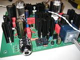
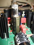
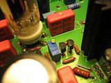
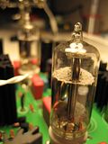
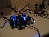
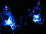
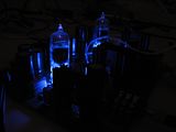
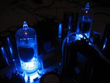
I spy the Bijou proto with Russian 6N6P double triode tubes, supplied by JeffR.
It can work but, ... there are several things that really need to be modified/improved (with all respect for the designer).
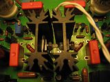
Most critical is the heatsink of Q2 on the PS, it's simply too small that probably not safe to use under full load
frown.gif
.
There is also no room on the board for a larger heatsink... so I think I go P-P.
 
Oct 29, 2007 at 7:21 PM Post #2,647 of 9,811
Hi Ferrari. You might be right about the heatsink. One reason why we're only prototyping now.

But, so that we don't miss anything, what else to you see? Better to fix now, if possible, than later.
smily_headphones1.gif
 
Oct 29, 2007 at 7:42 PM Post #2,648 of 9,811
Hi all... I have finished my first Millet Hybrid Maxed (or MAX as we know it better) built by me from a (very nice) Jrossel kit and I have made some pics...

I'll just post thumbnails here, but feel free to click on them for larger pics!

First some pics of the populated board and early biasing efforts... ah that feeling when first applying power and ... nothing blows, stinks or sizzles
biggrin.gif


I managed to actually get my MAX right the first time and as I very carefully biased (following the instructions on Tomb's site), I didn't ruin anything afterwards either (well, except for one fuse, but I quickly ditched the fuse completely and haven't had any probs since)


Some tube-shots ('cause I know y'all like 'em just as much as I do
wink.gif
)


PS: I liked that last 'nipple' so much it has become my avatar

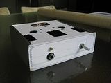
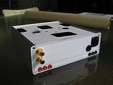
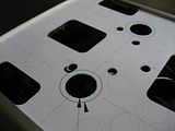
A decent amp deserves to be cased up nicely, so I decided to actually spend some work/time drawing out the layout and fitting it on the amp... I adapted Tomb's layout in Illustrator and pasted some printouts on cardboard, which leads to the OrigaMAX


Of course this was only a test and I drilled the alu plates as well (the cardboard version was a bit too flammable for safe use
wink.gif
) However I didn't really have the right tools for this and my work was a bit sloppy with some scuffing on the top plate as well
frown.gif


But I still had some metal screen left from my SR-60 recable-rescreen (see link in sig) and I soon devised an idea to 'fix' the outlook.


The screen wasn't completely flawless either and the sides of the top plate aren't as cleanly finished as I would have wanted, but in general it looks great and the flaws are only obvious from close-up. Also my IC's (while they work perfectly) look kinda bad from behind as I didn't have the right diameter heatshrink to finish them...

The MAX sounds great (with 12FK6 tubes) and the test points on the back and biasing holes on the top make for easy biasing without opening her up...

Thanks to all who had a part in bringing this project to life/making it accessible to me...
 
Oct 30, 2007 at 4:01 PM Post #2,649 of 9,811
Pics taken from the Millett MAX thread.

Here are my first set of external pics. Unfortunately it was hard to get all the dust off the case, but il try again when i get the internal pics.

I think the bright sun gives some cool effects
biggrin.gif


dsc06238db9.jpg


dsc06240mr1.jpg


dsc06237qm5.jpg


dsc06236nv0.jpg


imgp0074wq4.jpg
 
Oct 30, 2007 at 4:01 PM Post #2,650 of 9,811
ahhh feck internet going wrong
 
Oct 30, 2007 at 4:34 PM Post #2,651 of 9,811
Nice build, I like the window in the back.
wink.gif
 
Oct 30, 2007 at 4:44 PM Post #2,652 of 9,811
Quote:

Originally Posted by philodox /img/forum/go_quote.gif
Nice build, I like the window in the back.
wink.gif


Thanks. Ive decided to leave it as a gaping hole as any mesh or other window type material will impede heatflow, and the voltage regulator heatsink at the back is already nearly too hot to touch. The hammond case acts like a nice heatsink too
icon10.gif


Il get some better pictures up in due course, especially of the internal parts as i really want o show it off. No expense has been spared and ive used boutique parts all around.
 
Oct 30, 2007 at 9:13 PM Post #2,653 of 9,811
Quote:

Originally Posted by runeight /img/forum/go_quote.gif
Hi Ferrari. You might be right about the heatsink. One reason why we're only prototyping now.

But, so that we don't miss anything, what else to you see? Better to fix now, if possible, than later.
smily_headphones1.gif


Runeight, you are right… prototyping is indeed to discover things that we probably can modified/improved on a later version.
I will PM you soon with a small list of things on the Bijou proto that need a bit more attention (in some case a byte).
For now I can confirm that the Bijou proto works and sounds very good
600smile.gif
.
At some points, I deviate a bit from the original BOM..., however it also works with the original BOM.
(Heavier transformer; On the PS: off board heat sinks for Q1+Q2, 2400uF totally for C4+C5; On the amp board: C3+C4 are PIO and output capacitor C5 = MKP).

Unless the messy wirings and of course uncased (typical for proto works), It get more listening time than my recent built Millett Max... and you know why
wink.gif
.
 
Oct 31, 2007 at 1:25 AM Post #2,654 of 9,811
n1342260049_30089747_336.jpg

Completed speaker amplifier. It gets very loud, while staying clean.
 
Oct 31, 2007 at 2:06 AM Post #2,655 of 9,811
Quote:

Originally Posted by Televator /img/forum/go_quote.gif

...Of course this was only a test and I drilled the alu plates as well (the cardboard version was a bit too flammable for safe use
wink.gif
) However I didn't really have the right tools for this and my work was a bit sloppy with some scuffing on the top plate as well
frown.gif


A small file and some patience will do wonders for that top panel! You could add some silver grid to the heatsink holes for the looks!
wink.gif
 

Users who are viewing this thread

Back
Top