Millett "Starving Student" hybrid amp
Feb 26, 2009 at 5:47 AM Post #2,491 of 7,277
Quote:

Originally Posted by MoxMonkey /img/forum/go_quote.gif
looks great but is it just me or is there no power switch?


Interesting, totally forgot about the power switch. I don't think it could be in the pot, since its the same pot that was in the original P2P BOM.
 
Feb 26, 2009 at 7:45 AM Post #2,492 of 7,277
Quote:

Originally Posted by tomb /img/forum/go_quote.gif
Agreed, Nate. Those maybe just the ticket. I believe rds is working on a similar tack. The important thing to note for simplicity is that once the MOSFETs are bolted to the case lid, it shouldn't take any sort of elaborate mechanical connection to slap auxuliary heat removing devices on the lid.


Yes, I think I have just the ticket but since we don't have a dimensional board layout right now I'm not totally sure.
It would be fairly trivial to attach but would require a pdf template for trouble free assembly.
...now I just need to have that pcb show up.
 
Feb 26, 2009 at 1:05 PM Post #2,493 of 7,277
Quote:

Originally Posted by iareConfusE /img/forum/go_quote.gif
Looks clean and neat, good job. Mind making some printable templates for the front pot and output jack, please?


Thanks for the compliments. I have to be honest, when it comes to complicated top panels or back panels that are stuffed with components like the MAX I'm all for templates for helping people out. But this is two holes and all you have to do is stick the board in whatever slot you chose, measure the height and distance to the side and you're done. Also, I didn't use the slot that Tom recommended so my build is probably "non standard" and is at best still just a prototype.
Quote:

Originally Posted by MoxMonkey /img/forum/go_quote.gif
looks great but is it just me or is there no power switch?


No power switch. Didn't have one that I wanted to use so I finished it up without one. It will certainly be added later.
 
Feb 26, 2009 at 6:30 PM Post #2,494 of 7,277
Quote:

Originally Posted by n_maher /img/forum/go_quote.gif
Thanks for the compliments. I have to be honest, when it comes to complicated top panels or back panels that are stuffed with components like the MAX I'm all for templates for helping people out. But this is two holes and all you have to do is stick the board in whatever slot you chose, measure the height and distance to the side and you're done. Also, I didn't use the slot that Tom recommended so my build is probably "non standard" and is at best still just a prototype.
No power switch. Didn't have one that I wanted to use so I finished it up without one. It will certainly be added later.


Alright thanks anyway. Another question though. I've never used anything that utilized the terminal blocks. Obviously, the one labeled IN is for the sound input, but I notice there are two others that seem like 1 block of 4 terminals. I'm guessing one pair of terminals is for the switch, and the other for the DC input jack, but does it matter their hookup orientation apart from pos/neg (which I'm not even sure about since its labeled O1, O2) ? Ex: Can the dc power input be wired to the left block (of 2 terminals) or the right block?

Is the B+ and G markings supposed to be a label for something other than the switch?
 
Feb 26, 2009 at 6:51 PM Post #2,495 of 7,277
Quote:

Originally Posted by iareConfusE /img/forum/go_quote.gif
Is the B+ and G markings supposed to be a label for something other than the switch?


B+ is standard terminology for positive voltage. So, you connect the power to B+. G, similarly, is for the ground connection from the power supply. Switch is where you connect the two connectors from a SPST switch. The O1, O2, ... business are pin labels, much like an opamp socket might label pin 1 with no inherent meaning. If you use the terminal blocks, those labels will be covered anyway.
 
Feb 26, 2009 at 7:09 PM Post #2,496 of 7,277
Thanks for clearing it up for me Dsavitsk. Hopefully my last question: Is the standoff required? I'm not exactly sure how its used (even after reading the description off of Beezar). I know how its installed, I'm just unsure of its use.

thanks again.
 
Feb 26, 2009 at 11:58 PM Post #2,499 of 7,277
The pot only determines input impedance and how much it loads the source, it has nothing to do with the output of the amp (nor does the value of the pot have anything to do with the volume range, a 27k pot at halfway yields the same volume as a 50k pot at halfway, assuming the attenuation curve isn't different between them).

And @Vince: Needs moar blackgates.
 
Feb 27, 2009 at 12:12 AM Post #2,500 of 7,277
It's just a prototype Fitzy, moar BG's next time.
wink.gif
 
Feb 27, 2009 at 1:28 AM Post #2,502 of 7,277
I just hooked up my tube to a dc power supply to see if the heater worked (cheap thrill). at 19v the 2 heaters combined sucked 300 ma. That means the poor .38a 48v power supply is going to be working over 50% duty to keep everything going. No wonder it shuts down if you dont have at least 480uf on the ps line while the heaters warmed up.
 
Feb 27, 2009 at 1:54 AM Post #2,503 of 7,277
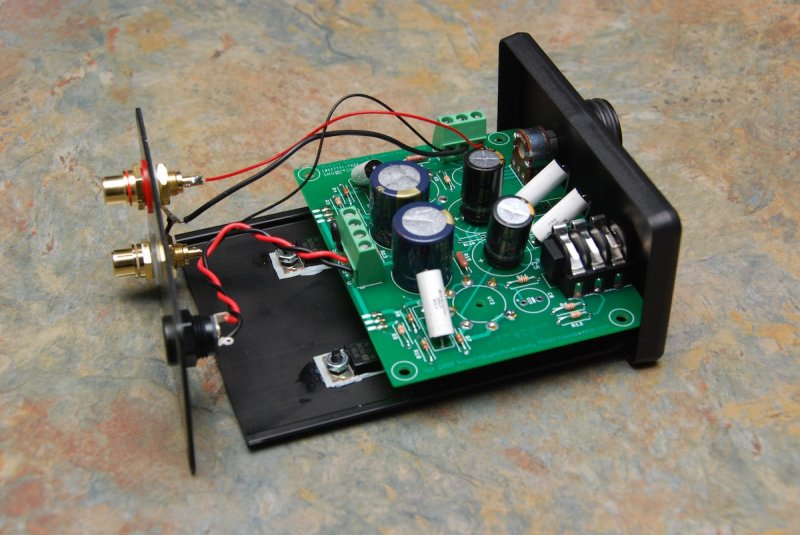
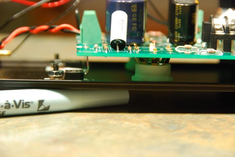
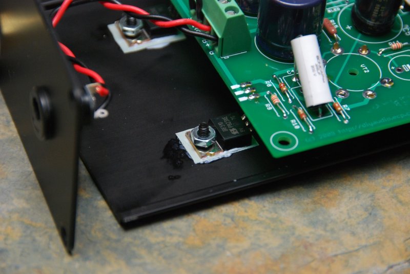
Thanks Dan! Here are a few internal shots along with a couple of notes:

1. If you're a beginning builder please do not try the smaller case that Tom has listed. As you can see the working room in side this case from top to bottom is pretty tight. Do yourself a favor, use the larger chassis and some room to breath.

2. Please note that I had to flip the orientation of the input terminal block. Facing out as it was when I first installed it made it impossible to get the board into the case with wires coming out.

109623529.jpg


109623528.jpg


109623527.jpg


If I have time tonight I'll set the amp up running into a dummy load and take some thermal measurements after a few run time intervals. I had it going for less than a half hour last night but it certainly didn't overheat in that limited window.
 
Feb 27, 2009 at 5:43 AM Post #2,504 of 7,277
You're right, Nate - the bigger case might be the way to go. I've been getting a couple of e-mails from another prototyper who's been having a bit of trouble with the other case. It sounds like the tube sockets rise up above the case lid pretty high, which may not look too good. He also mentioned about the input terminal block clearance.

EDIT: Correct that - he's saying the actual board pads from the input terminal block rub in the slots - also R7 and R10. I'm sure Dsavitsk can correct all of this on the production boards, though.
smily_headphones1.gif
 
Feb 27, 2009 at 7:06 AM Post #2,505 of 7,277
Do you guys know any good sources for the tubes for this amp? I am looking into building one buy I can't find any tube sources without 4-6 week lead time.
 

Users who are viewing this thread

Back
Top