Millett "Starving Student" hybrid amp
Feb 16, 2019 at 9:07 AM Post #7,186 of 7,277
Hello everyone,

I read thru the last couple of posts regarding grounding issues. Ironically, I just completed assembly of my Kit from Tom and I seem to be having some issues that I could use some input on. When switching on the LED light up. This is while neither cover is screwed in. If I position the board and fasten the front plate (4 screws), it will power up find. If I then position the back plate into loose assembly (no screws), it will power on. As soon as I try and install ONE of the four back plate screws I no longer have power. I do intermittently hear aching when trying to install the back plate screws.

I have assembled the RCA posts in both configurations with white washer and w/o white washer (interior side). The white washers are used on the exterior of the panel. The anodizing has been removed from the back side. I used a dremel tool with a wire brush to remove vs. "scraping" with a knife or file.

Like many others this is my first build and have more of a mechanical background vs. electrical.

Thoughts or ideas would be appreciated!

Mike
 
Feb 16, 2019 at 11:43 AM Post #7,187 of 7,277
Hello everyone,

I read thru the last couple of posts regarding grounding issues. Ironically, I just completed assembly of my Kit from Tom and I seem to be having some issues that I could use some input on. When switching on the LED light up. This is while neither cover is screwed in. If I position the board and fasten the front plate (4 screws), it will power up find. If I then position the back plate into loose assembly (no screws), it will power on. As soon as I try and install ONE of the four back plate screws I no longer have power. I do intermittently hear aching when trying to install the back plate screws.

I have assembled the RCA posts in both configurations with white washer and w/o white washer (interior side). The white washers are used on the exterior of the panel. The anodizing has been removed from the back side. I used a dremel tool with a wire brush to remove vs. "scraping" with a knife or file.

Like many others this is my first build and have more of a mechanical background vs. electrical.

Thoughts or ideas would be appreciated!

Mike

hear aching

Outside of whatever "aching" means, it doesn't sound like a grounding issue to me. Instead, it sounds like the classic problem of assembling casework, only to cause a short.
  • Did you use heat shrink on any exposed leads? If not, the wire gets compressed and bends into different shapes when you push the casework together in assembly. This may not be apparent as you take it apart again, because the wire springs back into its original shape.
  • Or, you could be capturing some of the wiring inside one of the slots near the assembly screw. Screwing the screw in may touch an exposed lead or worse, cut into the insulation so that the screw touches the bare metal of the wire.
Look carefully at the wiring as you assemble and push the parts together. See if the wiring is bending such that an exposed part of the wiring is touching bare metal. Be very careful when you screw in the assembly screws. Look to see if any wiring is getting close to the slots and getting trapped by one of the screws.

P.S. If you look at my documentation on diyforums.org, you'll find that I tightly twist the wire so that there are no errant leads flopping around everywhere. You still have to be concerned, because the design of the SSMH PCB amplifier needs to have wire slack to assemble and dis-assemble. However, you can minimize the issues by twisting the leads into a few bundles, not many single pieces of wiring.
 
Last edited:
Feb 16, 2019 at 12:25 PM Post #7,188 of 7,277
Thanks for taking time to reply. I will take another look, but it seems everything should be ok. I did use shrink tubing in all of the locations suggested and shown in the instructions. One leg of each LED, and the signal connection for each RCA jack. Evidently I am restricted from posting pictures since I’m a newer member.

Thanks again for the help
Mike
 
Feb 16, 2019 at 1:13 PM Post #7,189 of 7,277
Thanks for taking time to reply. I will take another look, but it seems everything should be ok. I did use shrink tubing in all of the locations suggested and shown in the instructions. One leg of each LED, and the signal connection for each RCA jack. Evidently I am restricted from posting pictures since I’m a newer member.

Thanks again for the help
Mike
You didn't mention the power connections and whether they get compressed upon case assembly. Also, the signal wiring runs along the side of the PCB inside the case. If you haven't put a good bend in them where they connect to the terminal block, it's very likely that they will get caught in the slots on the side of the case.

Let us know and good luck!
 
Feb 23, 2019 at 10:53 AM Post #7,190 of 7,277
Has anybody built a source into your SS amp? Something like bluetooth, Raspberry Pi or something else? I have asked this question couple of years ago but did not get many replies. Hopefully, this has changed since then and somebody can provide some feedback. Ultimately, I would like to put Raspberry Pi Zero with Phat DAC into the same enclosure so I do not need external source. All would be controlled by the phone. I am just not sure about two different power supplies (48V for SS and 5V for RPi - grounding issues, hum, etc) and RPi's wi-fi range in an all aluminum enclosure.
 
Mar 2, 2019 at 9:26 PM Post #7,192 of 7,277
Nobody? No Starving Student amps with built-in sources?

No offense, but a DAC inside an amp is fairly obvious. You want one? Then put it in there. It's DIY, after all.

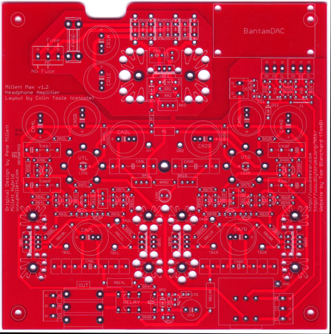
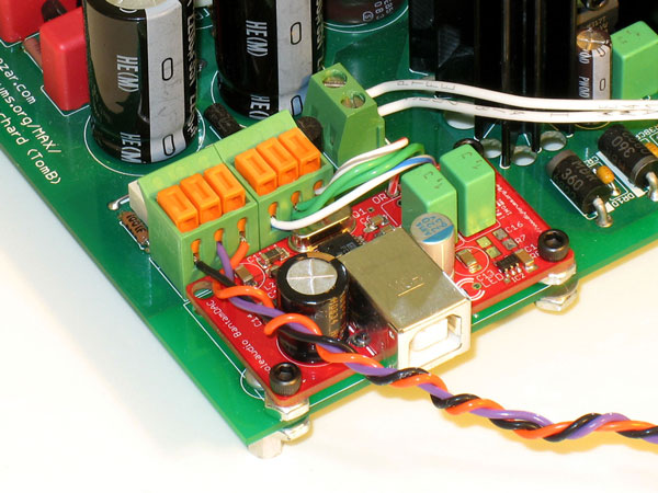
Allow me to note that the Millett Hybrid MAX V1.2 PCB has had an area identified for a DAC - either the GrubDAC, SkeletonDAC, or the BantamDAC, when we were still offering it. This DIY PCB has been in existence since 2010, I might add.

MOSFET-MAXoverlay-sm.jpg


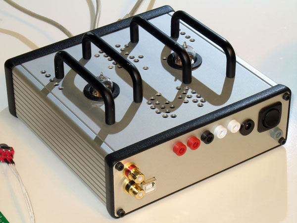
Here's a couple of pics of the board in action:
MOSFET-MAX-010-sm.jpg

MOSFET-MAX-03-sm.jpg


As for your idea of placing a Raspberry Pi, if the case has room - put it in there, too. It would have to be a lot more involved, because you'd probably need some sort of touch-screen interface, but you could probably make it work with some effort. I'm not sure that would be a real advantage, though, because then you'd be including the kitchen sink. AMB did an Arduino interface for his Gamma 3 DAC and it would only be a simple step after that to include an amp - assuming you used casework that was big enough.

There are several versions of the ODAC and O2 being housed together, too. Just look at JDS Labs or Mayflower Electronics. As long as you're using a USB-powered DAC, these are all pretty simple. It gets a lot more complicated when the DAC is high-end enough that it needs power. Then things get complicated enough that housing them in the same case has diminishing returns.
 
Mar 7, 2019 at 3:22 PM Post #7,193 of 7,277
You didn't mention the power connections and whether they get compressed upon case assembly. Also, the signal wiring runs along the side of the PCB inside the case. If you haven't put a good bend in them where they connect to the terminal block, it's very likely that they will get caught in the slots on the side of the case.

Let us know and good luck!

Hello,

I wanted to circle back. I have been using the amp successfully for a couple of weeks now with zero issues. Although, I never really identified root cause from my previously posted issue about a possible short. I spent a couple of days using it at work using my Iphone as a DAC source and powering thru a set of Beyerdynamic IME’s (idx 160’s). The SSMH replaced a Bravo V2 while auditioning at work.

The real reason I bought the SSMH was to keep at home and to use with a set of Sennheiser HD 6XX from massdrop (same as Sennheiser HD 650), and listen to my vinyl records. Here is where my challenges started up again. My turntable doesn’t have a built in pre-amp. That wasn’t a problem, because prior to buying my headphone set up I played my vinyl thru an Onkyo TX-NR1007 which had a phono stage built in. In addition to the phono stage, the Onkyo also has pre-outs. I think this is where I made the wrong assumptions and my novice level is being exposed. I planed on running my turntable through the phono pre-amp of my Onkyo then use the pre-outs on my RX to the SSMH to power my headphones… I found out quickly, it doesn’t work that way. I am now looking for a separate phono pre-amp to place in-between my turntable and my SSMH for a new listening experience.

I will eventually get something assembled.
 
Mar 8, 2019 at 11:34 AM Post #7,194 of 7,277
<snip>
I am now looking for a separate phono pre-amp to place in-between my turntable and my SSMH for a new listening experience.

I will eventually get something assembled.

The Hagtech Bugle is probably the highest quality, lowest cost phono pre-amp available. It's essentially an opamp phono pre-amp, but it will beat the pants off of almost any vintage receiver phono input or any small converter phono preamp you might buy on Amazon. The Bugle 2 is a PCB only, for $39 right now.

If you are really adventurous, Pete Millett has a no-capacitor-in-the-signal-path phono preamp design that you can buy from him on ebay. He has the bipolar power supply (assembled, complete!) for sale right now for $39 and the phono preamp board also assembled, even with the Cinemag inductors, for $59. You would still need to do the casework, but that's a helluva deal right now, IMHO. Keep in mind that the casework and grounding is a big deal with a phono pre-amp. The gain is so high that you will be lucky if you don't get hum at high volume levels. Separate casework between the power supply and pre-amp board is probably better. I didn't do that with mine. If I place it too close to anything with a transformer, it gets noisy. Other than that, it's fantastic. You'd probably have to spend $1-$2K to get better sound than Pete's design. Just the idea of RIAA equalization without capacitors in the signal path is outstanding.

Here is Pete's website detailing the LR Phono Preamp design and building instructions:
http://pmillett.com/LR_phono.html

Here is the Bipolar Power Supply (assembled!) on ebay:
https://www.ebay.com/itm/Pete-Mille...048138?hash=item23b798030a:g:JPIAAOSwiAFcfs8q

Here is the Millett LR Phono Preamp (assembled!) on ebay:
https://www.ebay.com/itm/Pete-Mille...035947?hash=item23b797d36b:g:zuEAAOSwzMlcfs~U

It's more than helpful that Pete has the PCB assembled. Some of us went through a number of extra AD797 opamps before finding the right ones that made the circuit stable. Again, that's another quirk of working with phono pre-amps. The gain is so high, that even manufacturing tolerances among the same opamps are enough to throw the circuit off.
 
Last edited:
Mar 8, 2019 at 11:42 AM Post #7,195 of 7,277
On the Raspberry Pi idea, would placing a wireless antenna in that proximity to the tubes not present a huge potential for interference?
 
Mar 10, 2019 at 8:13 PM Post #7,197 of 7,277
AD8397 is no go with NuHybrid. Made DIY dual2single adapter but the opamp is oscilating, heating a lot.

Unless I'm lost, this is the Starving Student thread, not Pete's NuHybrid thread.

Oh - by the way: the AD8397 will oscillate in even friendly opamp sockets, much less the NuHybrid. Typically, a custom layout and circuit is required to use an AD8397 without oscillation. They should probably outlaw the use of Brown Dog with an AD8397.
 
Mar 10, 2019 at 8:51 PM Post #7,198 of 7,277
Unless I'm lost, this is the Starving Student thread, not Pete's NuHybrid thread.

Oh - by the way: the AD8397 will oscillate in even friendly opamp sockets, much less the NuHybrid. Typically, a custom layout and circuit is required to use an AD8397 without oscillation. They should probably outlaw the use of Brown Dog with an AD8397.
Right, I mixed up threads :) thanks for pointing this and the tip.
 
Mar 11, 2019 at 5:09 PM Post #7,199 of 7,277
On the Raspberry Pi idea, would placing a wireless antenna in that proximity to the tubes not present a huge potential for interference?
Well, I guess I will have to try and report my findings. The wi-fi adapter is usb so if I position the raspberry strategically, it could be outside of the case. My new enclosure will have the tubes inside the metal case so it should be separated from the antenna.
 
Mar 24, 2019 at 4:20 PM Post #7,200 of 7,277
Hi, i am fresh new and i am starting learn to make a quite good ampli for my grado sr60....
Mostly the question is about the powersupply. The only good powersupply i can find in my local is a 33vdc from hp printer.. Can 33v can do well with this build (i using 12au7 mod by Dsavisk) ? .
I plant to use pcb (which i do by myself) so Do it have any advices for me to prevent the hum (i tried to build cmoy before and it comes with huge hum and noise ...).
 
Last edited:

Users who are viewing this thread

Back
Top