Little Dot MK8SE / MK6 Super Mods (All verified mods are on first page)
Dec 9, 2018 at 8:32 AM Post #3,541 of 4,154
... both meter light on togather and only left meter read 30, right meter read nothing, then suddenly smoke come out from PSU caps 330uF/250V..

Sorry when I said your 30mA looks wrong, I forgot you are using 7236's in which case the reading is OK for the left channel.
 
Dec 9, 2018 at 5:13 PM Post #3,543 of 4,154
Make sure it's not the caps charging when you use your ohmmeter meter you have to leave it connected for a while
 
Dec 13, 2018 at 6:17 AM Post #3,544 of 4,154
Make sure it's not the caps charging when you use your ohmmeter meter you have to leave it connected for a while
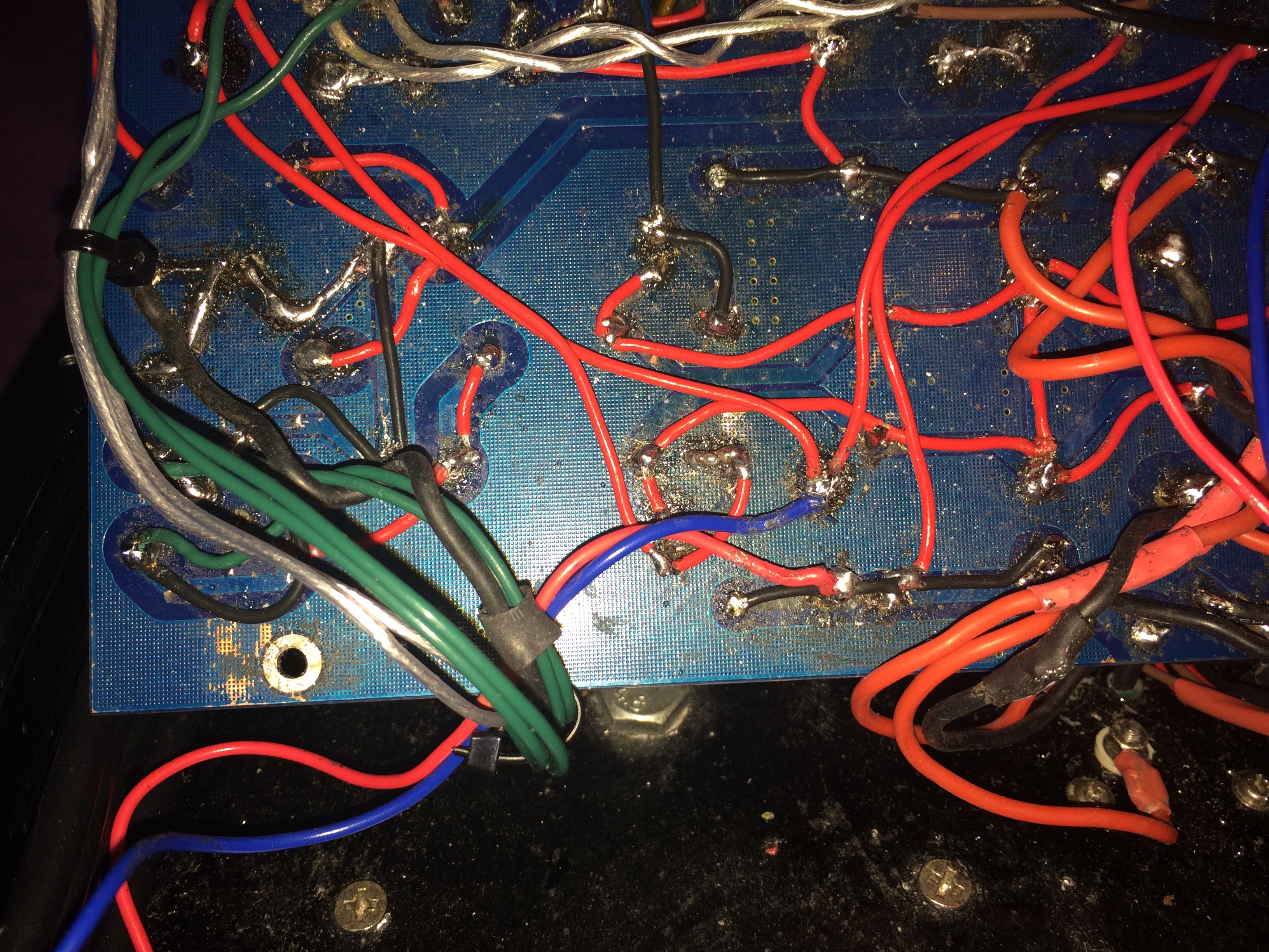
Hi! What do u think about the amp's Spaghetti wire from picture below? Are there any risk of short circuit, dangerous of high heat, burn smoke smell or over current explosion?
So far I have never seen anyone will do this way and I guess no one will agree or accept this type of ugly mod as well. LOL

IMG_9424.JPG
IMG_9426.JPG
IMG_9427.JPG
IMG_9428.JPG
IMG_9429.JPG
IMG_9430.JPG
IMG_9431.JPG
 
Dec 13, 2018 at 12:09 PM Post #3,545 of 4,154
Hi! What do u think about the amp's Spaghetti wire from picture below?

What's the reason for this?

Are there any risk of short circuit

Some risk.

dangerous of high heat

Very unlikely.

burn smoke smell

Use teflon wire in the future.

or over current explosion?

Absolutely not.

So far I have never seen anyone will do this way and I guess no one will agree or accept this type of ugly mod as well. LOL

PCBs, never again. P2P forever. Sorry not useful comment.
 
Dec 13, 2018 at 3:13 PM Post #3,546 of 4,154
What's the reason for this?


Some risk.


Very unlikely.


Use teflon wire in the future.


Absolutely not.


PCBs, never again. P2P forever. Sorry not useful comment.
Yes, those are Teflon wire and some Enamel copper wire on the op-amp gain resistor.
The reason is because most of trace on this board are damaged and seriously broken.
I understand shouldn't work this way, just want to get some opinion & advice.
I think is time to learn P2P and prototype method
 
Last edited:
Dec 13, 2018 at 4:26 PM Post #3,547 of 4,154
Yes, those are Teflon wire and some Enamel copper wire on the op-amp gain resistor.
The reason is because most of trace on this board are damaged and seriously broken.
I understand shouldn't work this way, just want to get some opinion & advice.
I think is time to learn P2P and prototype method
I’m sorry but that board just look like... well...
If you ever get that amp working I’d be impressed let’s put it that way. Please don’t take offense I don’t mean to be rude but it looks like you have set that board on fire, more than once!

I also see a mills 5w cathode resistor that looks burnt. Those should not look like that.
 
Dec 14, 2018 at 10:03 AM Post #3,548 of 4,154
I’m sorry but that board just look like... well...
If you ever get that amp working I’d be impressed let’s put it that way. Please don’t take offense I don’t mean to be rude but it looks like you have set that board on fire, more than once!

I also see a mills 5w cathode resistor that looks burnt. Those should not look like that.
I had tried to fix many times however still never work, as the components had been taken in & out a lot of times during troubleshooting
and cause the PCB trace damaged.
The Mills resistor is not burnt, actually is the surface get heat from soldering gun accidentally, all components have been checked
before put into PCB.
 
Dec 14, 2018 at 10:19 AM Post #3,549 of 4,154
If you like this amp a lot (and it's a decent amp I'm sure), why not make a scratch build of it?

That would work as an excellent springboard towards a DIY hobby (since you've already got one foot in that hobby), and then you'd have a working backup amp always, and a good enough reference amp for your future endevours.

Get a bit bigger chassis, and go P2P. Only portion that really 'needs' to be on PCB is the servo section. Rest is just fine P2P if done properly.

It's not that complicated a schematic.The Modern amp designed by me and presented here by Sonic is much more complicated and it can be done P2P no problem. Take it as a challenge.
 
Dec 14, 2018 at 5:59 PM Post #3,550 of 4,154
If you like this amp a lot (and it's a decent amp I'm sure), why not make a scratch build of it?

That would work as an excellent springboard towards a DIY hobby (since you've already got one foot in that hobby), and then you'd have a working backup amp always, and a good enough reference amp for your future endevours.

Get a bit bigger chassis, and go P2P. Only portion that really 'needs' to be on PCB is the servo section. Rest is just fine P2P if done properly.

It's not that complicated a schematic.The Modern amp designed by me and presented here by Sonic is much more complicated and it can be done P2P no problem. Take it as a challenge.
Yes, I have studied P2P quite some times already, looked for samples of pictures & videos everywhere, learned how other people design their works.
However I still can't find any suitable chassis yet, beside that, most of the spare parts and component I already have in hand
 
Dec 15, 2018 at 5:37 AM Post #3,551 of 4,154
This should do it: https://www.hammfg.com/part/1444-17123?referer=1236

I don't know about your local availability, but it's cheap enough with overseas shipping. It should be available locally also; if Hammond has a direct sales rep even in Finland (Uraltone, 100m from my home), I'm sure you do as well.

If one is not enough, get two; one for PSU, one for signal. Final looks are determined by your own efforts, I am personally satisfied with just a coat of spray paint and spray laquer. Maybe some wood around it.
 
Dec 15, 2018 at 10:11 AM Post #3,552 of 4,154
This should do it: https://www.hammfg.com/part/1444-17123?referer=1236

I don't know about your local availability, but it's cheap enough with overseas shipping. It should be available locally also; if Hammond has a direct sales rep even in Finland (Uraltone, 100m from my home), I'm sure you do as well.

If one is not enough, get two; one for PSU, one for signal. Final looks are determined by your own efforts, I am personally satisfied with just a coat of spray paint and spray laquer. Maybe some wood around it.
I have just ordered one exact same size as original chassis,plan to extend its height https://au.element14.com/hammond/1444-14103/enclosure-chassis-alum-unfinished/dp/2493435
Thanks for the info anyway
 
Dec 16, 2018 at 8:47 AM Post #3,553 of 4,154
Spaghetti wiring is no problem and indeed you should have twisted your heater wiring as twisting is good.

As long as resistor work it but also be careful not to scratch surface of those wire-wound resistors as that can break them.
 
Dec 16, 2018 at 8:50 AM Post #3,554 of 4,154
There is a thru-hole connection in middle of power supply that gets easily broken when replacing parts, leaving the PSU broken.
It is in the center connections and was talked about here with another member..
So check you have continuity in PSU from the big caps to before the diodes section in center trace.
 
Dec 16, 2018 at 8:53 AM Post #3,555 of 4,154
That looked like alot of unnecessary wiring as the board trace still there...
 

Users who are viewing this thread

Back
Top