


shaneotool
100+ Head-Fier
- Joined
- Jan 4, 2009
- Posts
- 106
- Likes
- 13
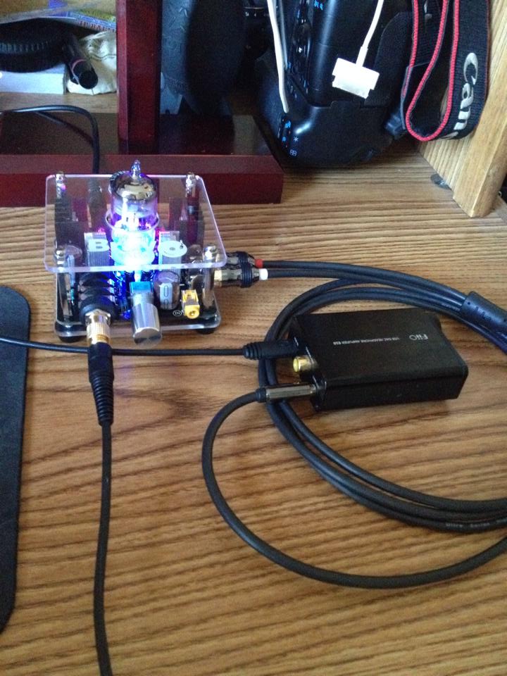
I don't really know what's going on these last few pages with the mod discussion on these amps, but I have a stock one - 12AU7 version - and it sounds great.
I dont have a soldering iron and don't plan on doing anything to it - just tought I'd throw this post in there in case someone reading this thread thinks you have to do all kind of work to make it sound good...
I dont have a soldering iron and don't plan on doing anything to it - just tought I'd throw this post in there in case someone reading this thread thinks you have to do all kind of work to make it sound good...