


Avro_Arrow
MOT: Soundwerx Designs
- Joined
- Apr 8, 2010
- Posts
- 2,211
- Likes
- 56
I don't think the difference in tolerance is going to make any difference...it does not need to be an exact value.
The power bypass cap (the one right behind the power connector) is the same height as the power connector.
The 10,000uF power cap (the one between the power connector and power switch) that Judge Buff is using is
as tall as the tube so you will not be able to use the top plastic cover if you install this mod.
Also installing the Bias caps is going to make the bottom plastic useless as well. You end up
with an amp that sits up on little legs.
You can set the Bias for 17 volts on the anode of the tube for each channel. After listening for a while it seems to
give the best sound even if it does not give the largest voltage swing. Anywhere between 15 and 17 volts at the
anode seems to work well.
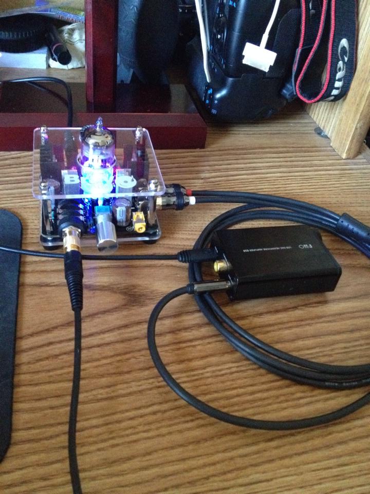
Here is a picture of mine...I have not installed the upgraded electrolytics yet, they will have to wait for my next
order. I have upgraded the MOSFET to IRF510, Changed the Bias adjust to 2K multi turn pots, replace the power
bypass cap with 1uF Film and installed the Bias caps (they are on the bottom of the board).

Quote:
The power bypass cap (the one right behind the power connector) is the same height as the power connector.
The 10,000uF power cap (the one between the power connector and power switch) that Judge Buff is using is
as tall as the tube so you will not be able to use the top plastic cover if you install this mod.
Also installing the Bias caps is going to make the bottom plastic useless as well. You end up
with an amp that sits up on little legs.
You can set the Bias for 17 volts on the anode of the tube for each channel. After listening for a while it seems to
give the best sound even if it does not give the largest voltage swing. Anywhere between 15 and 17 volts at the
anode seems to work well.
Here is a picture of mine...I have not installed the upgraded electrolytics yet, they will have to wait for my next
order. I have upgraded the MOSFET to IRF510, Changed the Bias adjust to 2K multi turn pots, replace the power
bypass cap with 1uF Film and installed the Bias caps (they are on the bottom of the board).
Quote:
The difference in those caps is the original is 5% tolerance and the new link you posted has a 10% tolerance.
On another note, my amp started making noise in the right channel. I thought it was a tube pin problem but it turned out to be a bias problem. I had 7 volts in the right channel and 8 volts in the left at the output cap. I readjusted to 12.04 volts which was the closest I could get. What a difference now. Not only is the noise all gone but the dynamics have opened up dramatically. The sound stage is way out there now and I can hear things I couldn't before. I guess the mods even make it better.
I'm gonna buy those 10% caps and get my order filled. I don't think a 5% tolerance will make a difference for the bypass cap.
Also A_A, you mention that the big PS filter cap just fits. Does it fit through the plastic cover where the original pops out of? Or does it just fit the board?

