


Handy Ray
New Head-Fier
- Joined
- Apr 12, 2007
- Posts
- 44
- Likes
- 10
Quote:
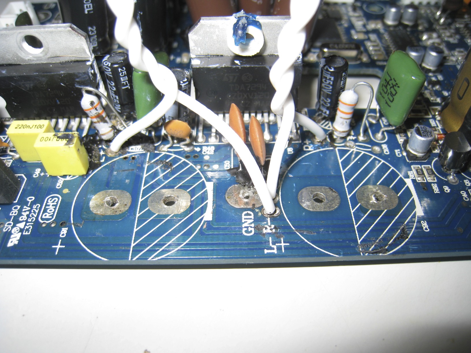
These are some of the more representative pictures I took of the stock amp plate. Based on what the OP's mods look like, it appears (to me) that the OP installed the Wima caps in place of some existing polyester caps (in yellow in the pictures) and through-hole ceramics. There were also some through-hole ceramics that you can't see in my pictures, but do see in OP's pictures from a different angle. I am not convinced that these PARTICULAR ceramics that are through-hole should have been replaced by films (mainly because I can't remember their function in their circuits, my current guess is that they are NOT rail bypass/decoupling caps, as all existing rail bypass/decoupling caps are polyester films). The other green ones (seen clearly in OP's pictures) are fine with either the stock polyesters or polypropylenes. The other through-hole electrolytics around this area (the chip-amps section) are for boot-strapping the amp chip and AC coupled-feedback. The boot-strapping capacitors are absolutely irrelevant to the sound quality (one set of 22uf caps, if I remember their values), and the other set of AC-coupled feedback can be changed in theory for something more audio-suitable. Based on what the OP said, it was wise to replace them anyway, as the stock caps suffer from "bad caps" symptom and will eventually vent and become unusable (as per experience with AudioEngine A5's). Replacing the polyesters that were stock with the polypropylenes MIGHT yield a small improvement in theory, but who knows if this is big enough to be noticed.
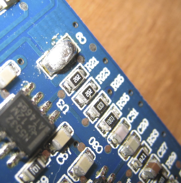
The ceramics you see in OP's and my pictures that are at the lower bottom of the PCB and are surface mount are responsible for 3 duties, there was a ton of power rail bypassing/decoupling for each op-amp, and I think some for compensation of the op-amps (can't remember this one), and the larger ones that are 10uf each are for signal coupling. I would advise to shunt the signal coupling caps here (SMD ceramics) as part of my mod. Equivalently, at the right most side near the jumper connector, there are those polymers for signal coupling, that I advised to replace with some Silmics. Since there wasn't a bias voltage on these caps, I would recommend as I did, a set of these Silmics in back to back forming a bipolar capacitor.
There were NO SMD ceramics that were either replaced with Wimas, or replaced with Silmics. The relevant SMD ceramics that are signal coupling are shunted to allow DC-coupling between stages of the pre-amp. All rail bypass capacitors (such as the 4 polymers you see around the NJW volume control chip) are left alone in my mod, and are suitable in their applications.
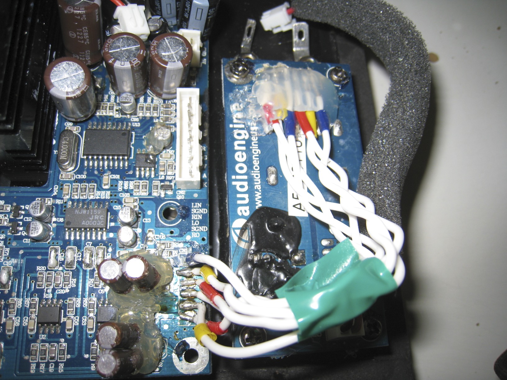
OP's amp plate showing where the red Wimas were installed:

Pictures of the Stock Amplifier plate from my images collection:


I hope this clears up everything that's been discussed thus far...
I speak mainly of the ceramics, there is more to specs than voltage and capacity. replacing them how you described will make the circuit performance worse. even replacing with the same type and increasing the capacitance may be worse by setting up resonances. as HF decoupling/bypass caps, the silmics (especially with long inductive leads like that) are completely useless, this isnt a subjective matter.
SMD ceramics have low impedance at high frequency and the fact they have no leads means they are very low inductance. the 'bipolar silmic' is practically the opposite of this and at high frequency they look almost like no caps at all, mostly inductive. genuinely high frequencies will simply pass them by, taking a short while to radiate RFI from the leads as they go. it looks a bit like a dipole antenna.
of course this isnt terrorism, but I do think people who illustrate technical mods on their blog have at least a small amount of due diligence to follow. realize that people less informed than you will look at your blog and perhaps incorporate another round of misinformation into it. its very easy to appear an expert online (even if you dont intend to present that way), even myself (I have no blog) I get messages all the time that assign me more depth of understanding than I have and as a publisher you should keep this in mind. otherwise real knowledge will become more and more diluted.
now of course we cant protect people from themselves....
Mr Jung most likely did not have point to point wiring in mind when suggesting this technique. Analogue circuitry was also not so full of VHF as it is today.
These are some of the more representative pictures I took of the stock amp plate. Based on what the OP's mods look like, it appears (to me) that the OP installed the Wima caps in place of some existing polyester caps (in yellow in the pictures) and through-hole ceramics. There were also some through-hole ceramics that you can't see in my pictures, but do see in OP's pictures from a different angle. I am not convinced that these PARTICULAR ceramics that are through-hole should have been replaced by films (mainly because I can't remember their function in their circuits, my current guess is that they are NOT rail bypass/decoupling caps, as all existing rail bypass/decoupling caps are polyester films). The other green ones (seen clearly in OP's pictures) are fine with either the stock polyesters or polypropylenes. The other through-hole electrolytics around this area (the chip-amps section) are for boot-strapping the amp chip and AC coupled-feedback. The boot-strapping capacitors are absolutely irrelevant to the sound quality (one set of 22uf caps, if I remember their values), and the other set of AC-coupled feedback can be changed in theory for something more audio-suitable. Based on what the OP said, it was wise to replace them anyway, as the stock caps suffer from "bad caps" symptom and will eventually vent and become unusable (as per experience with AudioEngine A5's). Replacing the polyesters that were stock with the polypropylenes MIGHT yield a small improvement in theory, but who knows if this is big enough to be noticed.
The ceramics you see in OP's and my pictures that are at the lower bottom of the PCB and are surface mount are responsible for 3 duties, there was a ton of power rail bypassing/decoupling for each op-amp, and I think some for compensation of the op-amps (can't remember this one), and the larger ones that are 10uf each are for signal coupling. I would advise to shunt the signal coupling caps here (SMD ceramics) as part of my mod. Equivalently, at the right most side near the jumper connector, there are those polymers for signal coupling, that I advised to replace with some Silmics. Since there wasn't a bias voltage on these caps, I would recommend as I did, a set of these Silmics in back to back forming a bipolar capacitor.
There were NO SMD ceramics that were either replaced with Wimas, or replaced with Silmics. The relevant SMD ceramics that are signal coupling are shunted to allow DC-coupling between stages of the pre-amp. All rail bypass capacitors (such as the 4 polymers you see around the NJW volume control chip) are left alone in my mod, and are suitable in their applications.
OP's amp plate showing where the red Wimas were installed:
Pictures of the Stock Amplifier plate from my images collection:
I hope this clears up everything that's been discussed thus far...


")
