Audioengine A5+ Speaker Upgrades

Apr 5, 2013 at 7:10 PM Post #91 of 127
Yes, I have the other white washer. 
I will be very careful with the coupling elna's, thanks for the heads-up.
 
Wait, which one is the 5V cable? Can it be seen in any of the photos on this thread? I may replace the wire connecting in input/output to the board but I haven't decided yet. I've come this far so... Is it worth the time to replace them in your opinion?
 
Damping is basically done, messy job. I'll let the silicon cure overnight while I finish the wiring this evening. 
 
Man you weren't kidding about this mod being time consuming..
 
Apr 5, 2013 at 7:55 PM Post #92 of 127
Good! Dont lose those washers, i almost lost one.

The 5V is only a 2 wire so you'll know which one it is right away.
It connects to the middle right side of the amp board.

The cables with 5-6 wires, i replaced all with silver plated copper 24AWG, as those are the ones carrying signal from the input RCA, 3.5mm, and output RCA.
Shouldn't be hard.
They're connected in order from left to right.
I felt as if i didn't do it, it would be a bottleneck, so i had it done.
I can't tell if it was worth it, as i did the mods all at one time.

I let the silicone cure for 2 days before playing loud music.

Yes, its very very time consuming, but the journey is a fun one, you learn lots, and at the end of it all you have improved sounding speakers which is great.
How long have you had your A5's?
If its quite awhile, you should be able to hear the differences instantly.
 
Apr 5, 2013 at 9:04 PM Post #93 of 127
Yes I see the wire you're referring to. I'll leave it be. Might as well replace the others being that they are part of the signal path. 
 
Question. The leads on the tweeters... I think I see a faint red mark on one of the two leads on each tweeter. I assume this indicates the + lead?? I ask because the red color looks like a faded marker or something.. not really obvious. Did you see this also?
 
I've owned these A5+'s for 2+ years now so yes, I'm very familiar with the sound. It seemed to me that the drivers and tweeters themselves are of a high enough quality to reflect the desired results from these mods. They're perfect for the small den they reside in. I use them with the aforementioned S8 along with a Schiit Bifrost. These speakers also handle home theatre duties so, being that I use them so much, I figured the mod was worth doing. Already upgraded the power cord (for DAC also... really made a difference to my ears) and I use quality cables (nothing too exotic.) I've beed using a Furman power conditioner as well (also used for guitar amp purposes and surge protection) so this seemed like a good next step.  
 
I'm learning as I go. I guess after all these "how" projects I may need to further educate myself in the "why" aspect. I know that the amp works but I don't know why, electrically speaking. Recommend any books/resources to better understand what the heck I am actually doing?
 
Apr 5, 2013 at 9:54 PM Post #94 of 127
etysmile.gif

Yes, leave that 5V alone, it's for the USB 5V charging dock.
 
Before removing the crimps on my tweeter, i used a sharpie to mark which was + and - so i could come back to it later.
 
I remember i checked with my multimeter before and the two spots seem to be bipolar (touch each other).
It should be safe to solder to whichever lead.
You can double check it just to be sure once you've semi-completed your mods.
Simply touch the wires onto the tweeter leads, and see which would make sound.
 
The silk dome is good stuff and so is the kevlar speakers.
Just like what Steve said before, it goes through a long process in which the parts become replace with cheaper parts in order for them to be able to market it at the price that they do, otherwise it would be very expensive.
Air Motiv's use high quality parts, and prices remain low, that's why it's popular nowadays.
Also their planar magnetic tweeter is great.
 
Ah, so you believe in cable differences.
I too change out my wall outlet and power strip with pure copper with a silver plating.
I use a custom cable on my A5+, it's shielded since i used a 3 Socket Mains Plug unlike the stock cable.
It took me awhile to look for a affordable C7 plug, and ended up getting one from Alibaba.
The Furutech ones are way expensive, i think $50+.
 
Here are a few links i like to help you understand more of DIY.
Parts and Components: http://www.sg-acoustics.ch/analogue_audio/parts/index.html
DIY: http://www.diyaudioblog.com/2011/08/custom-right-angle-double-shielded-iec.html
And once i've completed my website, you can drop by and there's some DIY Sections on there that can help you.
http://www.artemiscables.com/
I should have one soon for a DIY Sigma 11 power supply.
 
Tim
 
Apr 7, 2013 at 7:06 PM Post #95 of 127
So Im just about done. Before I start putting things back together I'd like to see the the amp is functional. How to I go about this with the multimeter?? I've check for continuity from the inputs to the crossover outputs and signal is going all the way though. But when I connected the left speaker to the crossover and powered up the amp I wasn't getting any sound. Power is being supplied, so far as i can tell, because the LED light comes up and it blinks when I turn the volume pot. I connected an iphone via both 1/8" and RCA to test but again, no music. But I was hearing some slight static when brushing the wires to the terminals on the driver.   
 
Do both speakers/crossovers need to be connected for everything to work?? I've checked for continuity in every place I could on the board... so I'm kinda stumped. What do I need to do to figure out what the problem is, if there even is one??? I'm at a loss.
 
Apr 7, 2013 at 7:51 PM Post #96 of 127
Quote:
So Im just about done. Before I start putting things back together I'd like to see the the amp is functional. How to I go about this with the multimeter?? I've check for continuity from the inputs to the crossover outputs and signal is going all the way though. But when I connected the left speaker to the crossover and powered up the amp I wasn't getting any sound. Power is being supplied, so far as i can tell, because the LED light comes up and it blinks when I turn the volume pot. I connected an iphone via both 1/8" and RCA to test but again, no music. But I was hearing some slight static when brushing the wires to the terminals on the driver.   
 
Do both speakers/crossovers need to be connected for everything to work?? I've checked for continuity in every place I could on the board... so I'm kinda stumped. What do I need to do to figure out what the problem is, if there even is one??? I'm at a loss.

 
Take the following pictures in birds eye view:
 
  • Where L- / L+ & R- / R+ is soldered.
  • Top left side of amp board where the large 3 pin from torroidal is plugged in.
  • Ceramic capacitor bypass solder (each one)
  • Panasonic FC/FR Area (to make sure their legs aren't touching anything metal)
  • Bipolar Capacitor area
 
I had that popping noise before.
You do not need both crossovers to be plugged in at the same time.
Make sure you distinguish your positive from your negative leads.
 
Also, for the cable that controls the LED and Volume, make sure if any wire ripped on inside of the speaker.
I had the issue where one wire ripped and the volume started at 1%, so turning up the volume, turns off the sound completely.


That's what im talking about.
That might be an issue.
 
What i did was:


If this isn't the case, Steve and i will help you find out whats wrong.
 
Tim
 
Apr 7, 2013 at 9:28 PM Post #97 of 127
Photos coming soon. In the mean time I think I found a problem. One of the tiny resistors ( I assume, labeled with "R") just next to the upper-most cap on the left side of the board is very loose and kind of burned. My own fault. I was impatient while desoldering in that area and I almost lost a soldering pad, was running on too-little sleep. Can I just bypass that tiny (and I mean tiny) resistor with a wire?? I'll upload a picture shortly.
 
Apr 7, 2013 at 10:08 PM Post #98 of 127
Quote:
Photos coming soon. In the mean time I think I found a problem. One of the tiny resistors ( I assume, labeled with "R") just next to the upper-most cap on the left side of the board is very loose and kind of burned. My own fault. I was impatient while desoldering in that area and I almost lost a soldering pad, was running on too-little sleep. Can I just bypass that tiny (and I mean tiny) resistor with a wire?? I'll upload a picture shortly.

Doesn't matter how tiny they are, their values can be very high, and that's what counts.
 
Use your multi-meter and measure in ohms each end of the resistor (does not need to be on) to see how much resistance they carry.
 
Start with 200 on the multimeter ohm scale and slowly go up from there, (2000, 20K, 200K, etc)
Once you find their value, buy a new one the same size from radio shack or some place online/nearby that sells "smd resistors".
You can show me a picture, and i'll tell you what size it is.
 
I melted a corner of a resistor too, but it was just a slight corner, thank god.
 
Tim
 
Apr 7, 2013 at 10:45 PM Post #100 of 127
Quote:
multimeter set to 20K gives a reading the hovers between 2.2 and 2.3. So the value is 2.2?? The resistor came off of the board... so lucky to have found it.

20K with a 2.2 or 2.3 reading means 2,200 or 2,300 ohms which is a decent amount, if you had shunted it = not good idea.
Have you tried doing it on 2K?
Anything higher than 2K would not be able to get measured, so 20K is the next closest.
I'm thinking its a 2200 resistor.
 
Does it have any marking on it?
If so, you can measure another one that's close to it, in order to find a closer exact value.
Please take a picture with it on the amp board so i can see what size it is.
It seems like a size 0805 or possibly 1206.
 
Tim
 
Apr 7, 2013 at 11:23 PM Post #101 of 127
Well I would except all of the sudden it's disappeared. The marking was gone anyway. It's so small, I don't think I'll be able to find it. Ugh. Anyways, there was no reading on 2K so I think you're right. It was the exact same size as the resistors in this photo, those 4 in a row. Dang, I thought I'd done everything right. Oh well. As long as it's something I can fix/replace then I'll live. Thanks for you help.


Apr 8, 2013 at 1:45 AM Post #102 of 127
i think the resistor I lost/melted had a 2202 marking on it. It was right next to a 47uf 50v cap, the upper-most of the four on the board. The three other caps with that value also have 2202 marked resistors right next to them. But the ohm readings on those resistors are not all the same, so I'm confused. The board # for it is half melted but I think its R49. Maybe I'll call Audioengine tomorrow and see if they can tell me the correct size and value. I don't know, maybe they will sell me a new un-capped board or something.  I hope I didn't destroy my speakers.
 
Does the resistor value need to be exact or just close?? 
 
Apr 8, 2013 at 4:48 AM Post #103 of 127
First, i would like for you to calm down.
It's not the end of the world.
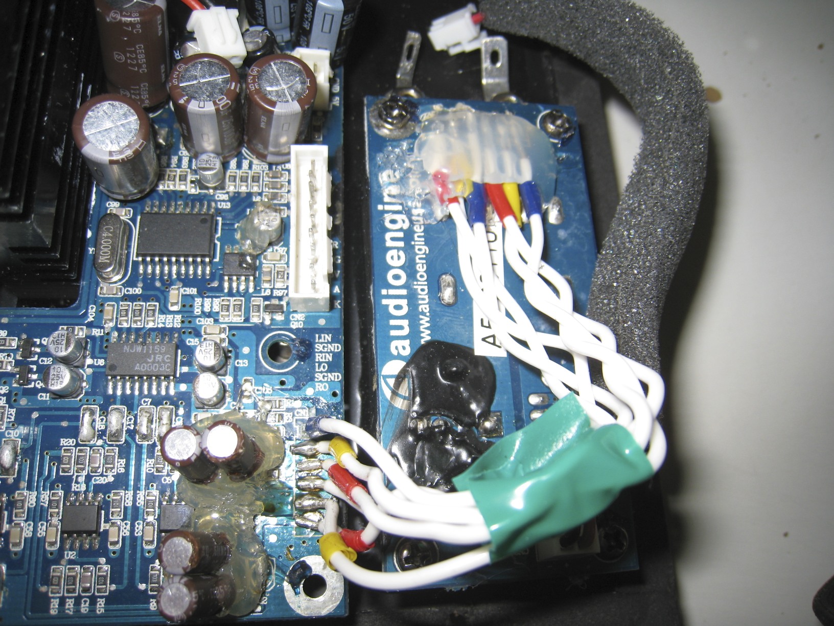
Losing a resistor would prevent the signal from passing, as there are no jumpers there (wire connecting one side to the other).
 
Thanks for the picture, but you should of sent me a picture of the actual spot that fell out, that way i can find it on my own speakers, and help you measure the resistance and tell you what to buy.
 
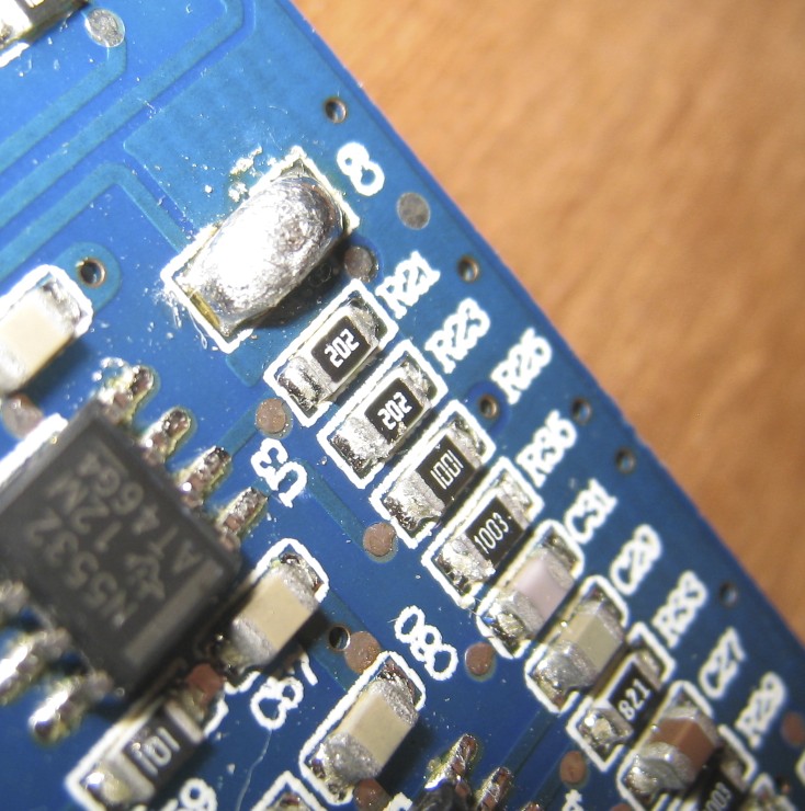
The reason why your multimeter shows 2,200-2,300 was because your set value was 20K measurement, which was far from the value of that capacitor, so reading was off.
It could also have been that multimeters generally degrade over time, and would need re-calibration.
 
Honestly, i think it could of been "2201" and not "2202".
Reason being, your measurement was 2.2 or 2.3 on a 20K scale which is a 2.2K estimate.
2201 is the code for a 2.2K resistor.
2202 is the code for a 22K resistor.
202 is the code for a 2K resistor.


If the resistor was big enough to fit 4 codes, it would be a 0805 or 1206.
I say you get a 2.2K resistor in SMD size 0805 and 1206 (just to be sure).
No need to contact Audioengine, this is a very easy fix my friend.
Just because it was placed next 22K resistors, doesn't mean it will be a 22K resistor.

It's ideal to replace it with the exact or near value.
You shouldn't go wrong with replacing it with 2K or 2.2K, but since you measured it and it proved to be 2.2K, then get a 2.2K resistor.
If you're still unsure, just tell me where it is, and i'll measure my own and tell you the size and where to buy it online.
 
Online: http://www.ebay.com/itm/100x-SMD-Chip-Surface-Mount-0805-Resistor-2-2k-ohm-222-/120823595088?pt=LH_DefaultDomain_0&hash=item1c21a5c050
If you live in the U.S., simple drive down to Radio Shack or anywhere like Fry's Electronics, they should sell resistors.
Find a 2.2K in the appropriate sizes i said above, or how large you saw it is and buy it.
 
When you solder it, first place it down where ideal, use a flat head screwdriver to push down on it, that way when the solder gets wet, it doesn't move the resistor.
Don't flow it for too long, as the metal ends can come out pretty easily if done too long.
 
After you're done, try it again.
If you still hear no sound, check for loose capacitor/resistors/ripped wires.
 
Tim
 
Apr 8, 2013 at 12:58 PM Post #104 of 127
Yes, yes you are right. Cooler heads prevail. I can fix this so no need for me to be freaked out. Thanks, I needed that proverbial slap-in-the-face:)
 
Ok, so here are two photos showing the exact location of the missing resistor. I'm pretty sure that it was the same size as the resistor just above the spot where the missing one was in the second photo. The board is pretty mangled right there, that's what I get for trying to force things. For what it's worth the rest of the board is clean, free of char, etc. But that spot has noob written all over it!!
 
I checked the hookup wire terminations (L+ L- R+ R-), the 3 pin plug for the transformer, ceramic bypass/shunts and the Panasonic cap area and they all look to be OK. No metal touching, no loss connections, no stray jumpers, etc. The polars caps are now sealed in hot glue but I was VERY careful with these, making certain that the solder points were solid, no legs touching anything else etc. Everything else on the board seems to be OK, but I guess I can't be completely sure until the speakers start singing again. One thing at a time..
 
I can find the parts I need down in Chinatown (I live in NYC) or certainly online if need be.  
 
Again, thanks. Seriously. 
 
(FYI, in the first photo you'll see that one of the wires (blue) for the input board connection is loose. This just happened as I was taking these photos. When I was testing the amp it was in place and working fine so that's not the problem.)


Apr 8, 2013 at 1:53 PM Post #105 of 127
It's most likely a 0805.
Size 1206 i'd expect to be as large as one of those R's on the top right of the pcb, but i could be wrong.

You should first clean up that soldering area with some rubbing alcohol or acetone with a q-tip/cotton swab as the appplicator.
That way its nice and clean, and that you won't mistakenly have the ends touching one another or anything else nearby.
That should be your main focus as of now.
Make sure to push firmly on the resistor when wetting each side using something by all means available.

The wires that you replaced connecting the amp and input/output board, you don't have them braided or twisted? Haha.
I have a picture on the first page showing how mine looks like.
Then again the distance is short anyway, so EMI shouldnt affect it as much.
I hope you checked continuity there before removing the wires for replacement.
If i remember correctly, they should go in order horizontally from left to right.
Double check that area to make sure that none of those soldered areas are touching one another, and you should be good to try firing on the speakers again after getting that resistor replacement.

For a DIY'er, anything is fixable as long as you can source the replacement parts, so don't freak out, its part of the learning curve.
Just think to yourself..."i can fix this $h1t".

The only thing im curious now is how your reaction would be to the new sound after having owned the speakers for nearly as long as i have.
Maybe you'll have the same opinion as i had under my Sound Review on page 1.

Keep up the hard work brother, it pays off in the end.
 

Users who are viewing this thread

Back
Top