Audioengine A5+ Speaker Upgrades
Jan 30, 2013 at 6:47 PM Post #46 of 127
Quote:
 
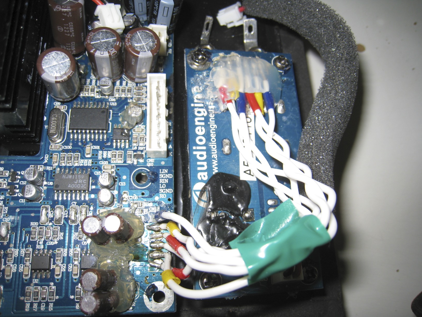
I rested my Silmics flat against the board (on top of some surface mount parts, if I remember correctly) and glued it down like that.
 
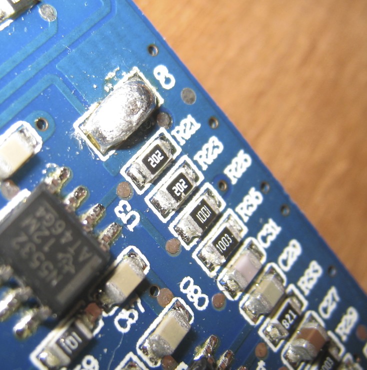
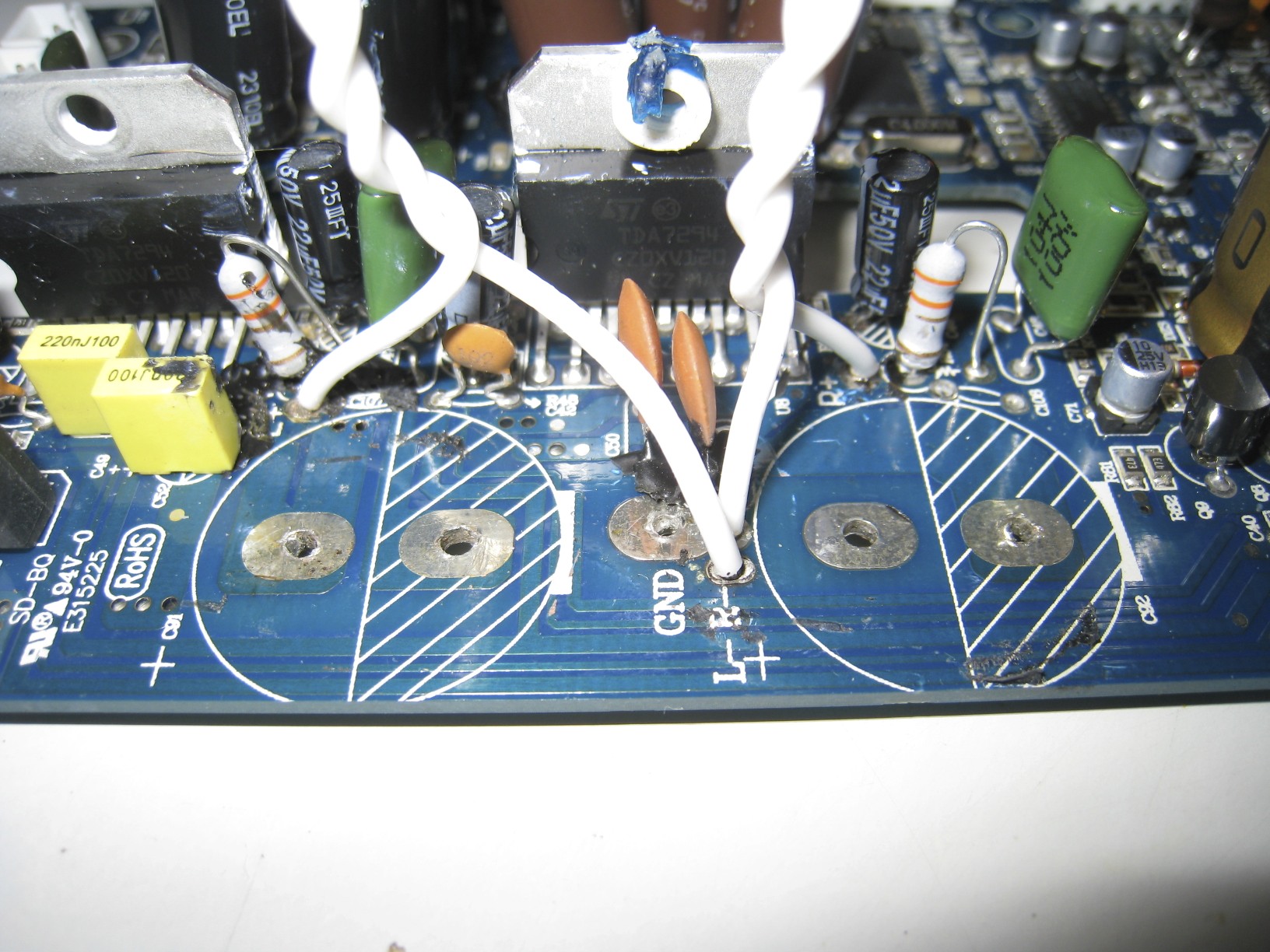
For the other caps that are through-hole, I noticed there is about 1 cm of room behind the board, so if you have too much crowding, or just want to make it easier, you can mount them on the reverse side.  I did that with a few things to free up some room on the top side.  Functionally identical.

1cm is kind of small eh? enough for a polymer cap. 
I'll most likely use a wire, as it seems to be the easiest way, but i'll have to see one i have the capacitors in hand.
 
To you and your friend, was the sound improvements that large? (After the polymer/ceramic bypass)
 
Jan 30, 2013 at 7:40 PM Post #47 of 127
Quote:
1cm is kind of small eh? enough for a polymer cap. 
I'll most likely use a wire, as it seems to be the easiest way, but i'll have to see one i have the capacitors in hand.
 
To you and your friend, was the sound improvements that large? (After the polymer/ceramic bypass)

The sound improvement was big to my ears.  I didn't have 2 sets to do A/B comparisons, but they definitely sounded better to 3 pairs of ears I had auditioning them on top of mine.
 
I'll post a picture sometime on how I managed to rig the 2 back to back caps onto a surface mount.
 
Jan 30, 2013 at 7:54 PM Post #48 of 127
Here is how I did my back to back Silmic II's soldered to a surface mount spot of the polymers at the input, demonstrated on an old dead video card:


And you want to ideally NOT use wires to lengthen the legs of the caps, because it introduces an extra un-shielded pathway for hum to be picked up from the large toroid right next to it, as well as other external sources and internal sources.  Keep the signal path short, as short as possible.  Anyways, this is what I did, replicated.
 
Jan 30, 2013 at 8:05 PM Post #49 of 127
Quote:
The sound improvement was big to my ears.  I didn't have 2 sets to do A/B comparisons, but they definitely sounded better to 3 pairs of ears I had auditioning them on top of mine.
 
I'll post a picture sometime on how I managed to rig the 2 back to back caps onto a surface mount.

I've had the A5 for a year and a half, this A5+ was my RMA due to the A5 making a tweeter static noise and sleeping even though my music was being played.
 
Strange enough, they upgraded me to the A5+, without the sleep feature, it was so much better. I'd gladly pay $100 more for that.
Having the A5/A5+ nearly 2 years now, i'm pretty sure i can hear even the slightest difference when plugging them in after the upgrade.
 
Can't wait to hear that big difference.
Quote:
Here is how I did my back to back Silmic II's soldered to a surface mount spot of the polymers at the input, demonstrated on an old dead video card:
And you want to ideally NOT use wires to lengthen the legs of the caps, because it introduces an extra un-shielded pathway for hum to be picked up from the large toroid right next to it, as well as other external sources and internal sources.  Keep the signal path short, as short as possible.  Anyways, this is what I did, replicated.

Ah so you soldered it that close. Okay now i understand. With it being that close, the bottom of the capacitor is now more flat, and can easily sit on the pcb.
 
What i'll do is put some hot glue, let it dry, put the two capacitors over, then glue the sides on. This way the two connecting legs does not touch anything metal from nearby chips/resistors/capacitors.
 
Seems simple enough.
 
Ended up getting these: http://www.mouser.com/Search/ProductDetail.aspx?R=RFS-25V220MF3%235virtualkey55500000virtualkey555-RFS25V220MF3%235
 
Jan 30, 2013 at 9:29 PM Post #50 of 127
You can also lay the capacitors on its side, so instead of standing up like that, turn them 90 degrees to lie on the board, the legs absolutely won't touch anything then.  I think that's how 1 of 2 sets of my Silmics were mounted to avoid the surface mounted parts. 
 
I guess Elna changed the packaging on the Silmics, they used to be brownish like in the picture (those are Silmic II's).
 
The A5+'s are a sweet upgrade.  The A5's were notorious for overheating under loud use or hot weathers.  The heatsink was internal, and didn't ventilate well.
 
Jan 30, 2013 at 9:39 PM Post #51 of 127
So.. you're "upgrading" the OS-CON capacitors for two ELNA Silmic II in series
 
And in another thread. Someone "upgraded" ELNA Silmic II for OS-CON.
 
It seems to me that all you're doing here is making the signal go trough 2 capacitors instead of a single one. Since OS-CON and ELNA Silmic II are debated to be the best capacitors on the market, we can conclude they are almost the same quality. That said, your "upgrade" is really a downgrade, since you're really doubling the distortion introduced by those capacitors.
 
Objectively, there is no way this can improve the sound. But then you're claiming that changing a couple inches of wires has a more significant influence on sound than damping in the speaker cabinet. So I'm just gonna conclude you're not being objective, and will leave you to your placebos.
 
But just as a final piece of advice: please don't go bypass components that you have no idea why they are there. A couple of pages back, someone tried to "correct" me by saying to bypass the capacitors. I was talking about the power decoupling capacitors, but this person spoke about the coupling capacitors. Let's just say bypassing one or the other won't give you the same end result.
 
Jan 31, 2013 at 2:25 AM Post #52 of 127
there is no way you have improved performance if those silmic are decoupling caps (well actually at this size they become reservoir caps), you do know that putting the 2 caps in series like that reduces the capacitance, rather than increasing it right? it only increases the voltage rating, which i'm guessing is not what you were trying to do? you will have created a 'cap' that is more inductive, higher impedance and most likely resonant.

SMD is the superior format for decoupling, hell these days its pretty much superior for everything, yes even audio.

edit: sorry I just read back, I see you know its lowered the capacitance value. it has also increased the impedance, which is now seen in series, so youve doubled the impedance of the silmics, which are already higher than the caps you are replacing.

silmics can be used well in some applications, mostly for if you have to use an electro in the signal path, which is why you would connect 2 together to make a bipolar cap to handle the AC signal, for DC it serves no purpose IMO (well unless degrading the specs is the purpose?).

it is done because there are not all that many high quality bipolar electros made anymore for audio (probably because most stuff is moving towards being DC coupled these days) and if a bipolar cap is needed for AC signal duties, most will use a film cap.

AC (alternating current) switches polarity twice each 'swing' so a polar cap can distort on the alternate phase, so if for AC signal and film cant be used, this trick was sometimes used to make a nice quality non-polar cap. This has no bearing whatsoever on decoupling DC power supplies.... for power supply reservoirs and decoupling, the SMD polymers you replaced are the better choice.

wow you are replacing ceramic HF decoupling caps with them too? just a little bit of info, even a small 0402 size ceramic capacitor placed directly across pins with via in pad pattern for the PCB (lowest possible inductance and impedance) is only good up to 10MHz.

the silmics are literally pointless for bypassing HF signals, the ceramics were orders of magnitude better for the job and even those were probably too large. For really effective digital HF decoupling, only even smaller SMD parts than 0402 (0201, like a spec of sand), as well as planar capacitance designed into the PCB power and ground planes is effective.

for getting rid of/attenuating such noise, a combination CRCLC is required. Something like the Murata EMIFIL products

it is clear, funnily enough, that audioengine have a better idea about how audio hardware and basic electronics functions than your friend. who woulda thunk that?
 
Jan 31, 2013 at 9:41 AM Post #53 of 127
Quote:
there is no way you have improved performance if those silmic are decoupling caps (well actually at this size they become reservoir caps), you do know that putting the 2 caps in series like that reduces the capacitance, rather than increasing it right? it only increases the voltage rating, which i'm guessing is not what you were trying to do? you will have created a 'cap' that is more inductive, higher impedance and most likely resonant.

SMD is the superior format for decoupling, hell these days its pretty much superior for everything, yes even audio.

edit: sorry I just read back, I see you know its lowered the capacitance value. it has also increased the impedance, which is now seen in series, so youve doubled the impedance of the silmics, which are already higher than the caps you are replacing.

silmics can be used well in some applications, mostly for if you have to use an electro in the signal path, which is why you would connect 2 together to make a bipolar cap to handle the AC signal, for DC it serves no purpose IMO (well unless degrading the specs is the purpose?).

it is done because there are not all that many high quality bipolar electros made anymore for audio (probably because most stuff is moving towards being DC coupled these days) and if a bipolar cap is needed for AC signal duties, most will use a film cap.

AC (alternating current) switches polarity twice each 'swing' so a polar cap can distort on the alternate phase, so if for AC signal and film cant be used, this trick was sometimes used to make a nice quality non-polar cap. This has no bearing whatsoever on decoupling DC power supplies.... for power supply reservoirs and decoupling, the SMD polymers you replaced are the better choice.

wow you are replacing ceramic HF decoupling caps with them too? just a little bit of info, even a small 0402 size ceramic capacitor placed directly across pins with via in pad pattern for the PCB (lowest possible inductance and impedance) is only good up to 10MHz.

the silmics are literally pointless for bypassing HF signals, the ceramics were orders of magnitude better for the job and even those were probably too large. For really effective digital HF decoupling, only even smaller SMD parts than 0402 (0201, like a spec of sand), as well as planar capacitance designed into the PCB power and ground planes is effective.

for getting rid of/attenuating such noise, a combination CRCLC is required. Something like the Murata EMIFIL products

it is clear, funnily enough, that audioengine have a better idea about how audio hardware and basic electronics functions than your friend. who woulda thunk that?

 
I don't think you have read the whole thread...   The Silmics II's are in a signal coupling situation, the ceramics that were surface mount were used for signal coupling (in my mod, as indicated by the pictures with circles around the caps), and the back to back config effectively forms a bipolar cap, getting rid of some distortion, i.e.,:
 
"If used as AC coupling capacitors (i.e. as high-pass filter) they do generate appreciable distortion at low frequencies. As a rough guidline I’d expect them to start with serious distortion (above 0.001 % at +20 dBu) at about 10x the cutoff-frequency. Or the other way round: choose the cutoff-frequency no higher than 2 Hz. At the same time this figure will mostly avoid time domain waveform distortion due to low-frequency phase shift. DC bias will increase distortion even more. Bipolar electrolytic capacitors (both as “true” bipolar capacitor or implemented with two polar ones back-to-back) show greatly reduced distortion and are recommended if space and cost allows their use. Obviously if used e.g. as smoothing or bypass capacitor in power supplies this distortion characteristic is far less problematic."
 
From the analog guru Samuel Groner, whose contributions to objective studies on a LARGE variety of opamps still enlightens us to this day.  Although this is fairly well known and textbook material. 
 
While I'm sure AudioEngine has a good assortment of knowledgeable engineers on staff, the product is a compromise between the engineering team, the cost-cutting admin-bean-counters, and the OEMs who actually manufacture the product.  ALL OF THESE PEOPLE gets a say on what the product should be designed like.  So many examples of corner-cutting resulting in substandard equipment that was engineered well are out there.  In fact, Centrance in their development blogs for the DacPort even said that the OEM making the DacPort wanted to substitute (among other things), a JRC opamp for the OPA1612 in their design to save a buck or two on a several hundred dollar product.  It took a lot of insistence from Centrance to get the OEM to stick to the plans by the engineers.  Pioneer's excellent Andrew Jones designed speakers is another example, where the engineers had to physically go down to the factory there they were made to MAKE SURE the speakers turned out they way they designed it, and wasn't tinkered with along the way. 
 
Jan 31, 2013 at 9:53 AM Post #54 of 127
Quote:
So.. you're "upgrading" the OS-CON capacitors for two ELNA Silmic II in series
 
And in another thread. Someone "upgraded" ELNA Silmic II for OS-CON.
 
It seems to me that all you're doing here is making the signal go trough 2 capacitors instead of a single one. Since OS-CON and ELNA Silmic II are debated to be the best capacitors on the market, we can conclude they are almost the same quality. That said, your "upgrade" is really a downgrade, since you're really doubling the distortion introduced by those capacitors.
 
Objectively, there is no way this can improve the sound. But then you're claiming that changing a couple inches of wires has a more significant influence on sound than damping in the speaker cabinet. So I'm just gonna conclude you're not being objective, and will leave you to your placebos.
 
But just as a final piece of advice: please don't go bypass components that you have no idea why they are there. A couple of pages back, someone tried to "correct" me by saying to bypass the capacitors. I was talking about the power decoupling capacitors, but this person spoke about the coupling capacitors. Let's just say bypassing one or the other won't give you the same end result.


First of all, the polymers were not OSCONs.  OSCON is one of Sanyo's brands if memory serves me correctly.  They are marked by Sanyo's markings.  These are who knows what make type of polymers.  Secondly, polymers are way better than electrolytics (typical electrolytics) at HIGH frequency, as in MHZ to GHZ range (and piss-poor at audible frequencies, particularly the bass region).  You see them in digital circuits all the time, motherboards, GPUs, etc.  However, polymers are terrible at coupling audio signals.  The fact that these were surface mount gives it away, the reason why you surface mount tank capacitors is mainly to reduce lead inductance at very high frequencies, typical of digital circuits.  This is the inappropriate choice here, since the frequency spectrum we're interested in coupling is far, far lower, where there are TONS of good coupling choices in terms of capacitors that way outshine polymers.  In this region, electrolyte distortion is the main consideration, where Silmics, Black Gates, etc are all optimized for.
 
For the 2 caps back to back, the reason is that the single caps are polarized, and one "pole" of that capacitor is responsible for a lot of distortion temporally (the cathode and anode are not equal in how much distortion they create, because fundamentally, the cathode and anode in a polar cap are different).  When you couple two of those capacitors together back to back, you form an effective bipolar capacitor with symmetric distortion products which minimizes the total distortion (if the capacitors are similar, which they are in this case).  But don't take just my word on it, ask Walter Jung and Samuel Groner, people we all should respect:
 
http://www.reliablecapacitors.com/pickcap.htm
http://www.sg-acoustics.ch/analogue_audio/parts/index.html
 
Lastly, the objectivity in my mods comes from the fact that AudioEngine chose to use inappropriate coupling capacitors.  Again, don't take my word on it, look at the links above and read up on ceramic capacitor distortion for yourself.
 
I have already investigated the circuit where I commented, all the positions I have adviced to shunt (or bypass with a wire) are signal coupling situations.  This is KNOWN to objectively improve the sound by eliminating capacitive distortions all-together if there is no DC on the lines, which I have also made sure of.  I never made mentions to shunt power supply bypass capacitors, I assumed the OP meant the same ceramics I talked about in my pictures, THEN LATER ON, the OP uploaded the pictures pointing out where he installed the MKPs and FKPs and I immediately replied on it.
 
Jan 31, 2013 at 4:48 PM Post #55 of 127
Yes.
 
Handy Ray (Steve) and I had a small misunderstanding regarding the ceramic capacitors for the power supply versus the signal coupling areas.
 
I mainly replaced those (film & ceramic), due to the hatred of those specific colors. and since i was upgrading many other things, i decided, why not?
Of course i had to change the tags to (Not Required) since it would be a waste of money for most people.
 
As for the polymer/ceramic bypass "upgrade". I had no intentions of doing this mod or even considered it, until i bumped into Steve's thread located at :http://www.diyaudio.com/forums/chip-amps/217335-audio-engine-5-amplifier-modifications.html and decided to ask for his assistance.
Due to his inactivity on the forums for years, i had high doubts of ever getting a reply from him, but something miraculous happened.
 
Anyways, i would not have done this upgrade, while being blindfolded (knowing very little about circuitry), if it wasn't for him. Since he's very knowledgeable on his subjects, and having done this mod to his own A5+ Speaker Set, in addition to hearing an improvement with 3 other individuals, i decided to go for it.
 
Even though this is my thread, and usually it's up to that person to know what they're doing and conduct the upgrades, Steve has been my catalyst throughout all this catastrophe.
Jacky's Audioengine A5+ Mod: http://www.xtremeplace.com/yabbse/index.php?topic=111705.0
Jacky who i also contacted on a few occasions, had given me help due to the various detailed pictures of the crossover upgrade.
 
I published the mod steps on my primary page, because i was sure that the objective was indeed an "upgrade".
I would not want to lead anybody astray.
 
Best Regards,
 
Timothy
 
Feb 1, 2013 at 9:20 PM Post #56 of 127
Handy Ray, I was commenting on the photos posted recently, since they were posted several times and people were talking about following recommendations and buying bunches of Elnas, I made the fairly reasonable deduction people would be replacing the 'crappy ceramics and SMD polymers' as is the current mode.

oscon has become the generic name for polymers it seems, I dont use it and I agree with you, terrible signal coupling caps and DC leakage is an issue, but myself I try first to build DC coupled, then film if I have to, I wouldnt use an electrolytic ever. I build from scratch mostly these days or with designs ive chosen, so I dont have to put up with bad decisions (of course I sometimes make them)

as a side note, there are some very good and very linear thin film SMD caps starting to appear, these will be a good alternative to film caps. ive used them for compensation and clock supply decoupling with very good results, but only available in small values as yet.

my apologies for the misunderstanding re the lineage of the photos, the photos were posted, a blog mentioned, conversations mentioned and odd decisions illustrated, so I replied to them. I wasnt aware the odd ones were cssarrow's.

cssarrow:

replacing them would be more than a waste of money for most people, replacing them in the way you describe is destructive, it doesnt just do no good, it does evil. Replacing caps because you dont like the colour and posting it on your blog? wow

I wasnt aware I had to read the entire thread when replying to a specific post asking for opinion..... out of due diligence I read back a couple of pages and edited my post.
 
Feb 1, 2013 at 9:51 PM Post #57 of 127
Quote:
Handy Ray, I was commenting on the photos posted recently, since they were posted several times and people were talking about following recommendations and buying bunches of Elnas, I made the fairly reasonable deduction people would be replacing the 'crappy ceramics and SMD polymers' as is the current mode.

oscon has become the generic name for polymers it seems, I dont use it and I agree with you, terrible signal coupling caps and DC leakage is an issue, but myself I try first to build DC coupled, then film if I have to, I wouldnt use an electrolytic ever. I build from scratch mostly these days or with designs ive chosen, so I dont have to put up with bad decisions

as a side note, there are some very good and very linear thin film SMD caps starting to appear, these will be a good alternative to film caps. ive used them for compensation and clock supply decoupling with very good results, but only available in small values as yet.

my apologies for the misunderstanding re the lineage of the photos, the photos were posted, a blog mentioned, conversations mentioned and odd decisions illustrated, so I replied to them. I wasnt aware the odd ones were cssarrow's.

cssarrow:

replacing them would be more than a waste of money for most people, replacing them in the way you describe is destructive, it doesnt just do no good, it does evil. Replacing caps because you dont like the colour and posting it on your blog? wow

I wasnt aware I had to read the entire thread when replying to a specific post asking for opinion..... out of due diligence I read back a couple of pages and edited my post.

Replacing it was my choice, and there's no negatives to this, i followed specs and only went a little higher. Even though this yields no benefits, it put on my blog, because after all, this is MY MOD, and i decided to share everything that i did.
 
To let people understand, i added the (Not Required) tag, so people would understand it's not needed and outputs ZERO gains.
 
Changing caps due to color approval is strange isn't it? Color choice man, color choice. Applies to cables too.
 
You were just trying to be helpful, and i appreciate that.
 
Best Regards,
 
Tim
 
Feb 1, 2013 at 10:09 PM Post #58 of 127
Cheers mate! 
 
What type of SMDs are you referring to that are coming out these days ?  I'm going to evaluate some PPS caps against MKPs or PPs (non-metalized polypropylene) for signal coupling when possible in the future.  I have only used PPS film caps for compensation and filters, and seen them once (assuming they are PPS) in a Pedja Rogic built Aya II dac for the resistor-ladder DAC chip.  Or are you referring to some other technologies ?  I have once heard that niobium oxide caps are supposed to be great with the pros of tantalums, but none of the drawbacks, but then haven't heard anything on them since. 
 
 
Quote:
Handy Ray, I was commenting on the photos posted recently, since they were posted several times and people were talking about following recommendations and buying bunches of Elnas, I made the fairly reasonable deduction people would be replacing the 'crappy ceramics and SMD polymers' as is the current mode.

oscon has become the generic name for polymers it seems, I dont use it and I agree with you, terrible signal coupling caps and DC leakage is an issue, but myself I try first to build DC coupled, then film if I have to, I wouldnt use an electrolytic ever. I build from scratch mostly these days or with designs ive chosen, so I dont have to put up with bad decisions (of course I sometimes make them)

as a side note, there are some very good and very linear thin film SMD caps starting to appear, these will be a good alternative to film caps. ive used them for compensation and clock supply decoupling with very good results, but only available in small values as yet.

my apologies for the misunderstanding re the lineage of the photos, the photos were posted, a blog mentioned, conversations mentioned and odd decisions illustrated, so I replied to them. I wasnt aware the odd ones were cssarrow's.

cssarrow:

replacing them would be more than a waste of money for most people, replacing them in the way you describe is destructive, it doesnt just do no good, it does evil. Replacing caps because you dont like the colour and posting it on your blog? wow

I wasnt aware I had to read the entire thread when replying to a specific post asking for opinion..... out of due diligence I read back a couple of pages and edited my post.

 
Feb 1, 2013 at 10:10 PM Post #59 of 127
Replacing it was my choice, and there's no negatives to this, i followed specs and only went a little higher. Even though this yields no benefits, it put on my blog, because after all, this is MY MOD, and i decided to share everything that i did.

To let people understand, i added the 
(Not Required)
 tag
, so people would understand it's not needed and outputs ZERO gains.


Changing caps due to color approval is strange isn't it? Not as strange as 9/11 though.


You were just trying to be helpful, and i appreciate that.


Best Regards,


Tim


I speak mainly of the ceramics, there is more to specs than voltage and capacity. replacing them how you described will make the circuit performance worse. even replacing with the same type and increasing the capacitance may be worse by setting up resonances. as HF decoupling/bypass caps, the silmics (especially with long inductive leads like that) are completely useless, this isnt a subjective matter.

SMD ceramics have low impedance at high frequency and the fact they have no leads means they are very low inductance. the 'bipolar silmic' is practically the opposite of this and at high frequency they look almost like no caps at all, mostly inductive. genuinely high frequencies will simply pass them by, taking a short while to radiate RFI from the leads as they go. it looks a bit like a dipole antenna.

of course this isnt terrorism, but I do think people who illustrate technical mods on their blog have at least a small amount of due diligence to follow. realize that people less informed than you will look at your blog and perhaps incorporate another round of misinformation into it. its very easy to appear an expert online (even if you dont intend to present that way), even myself (I have no blog) I get messages all the time that assign me more depth of understanding than I have and as a publisher you should keep this in mind. otherwise real knowledge will become more and more diluted.

now of course we cant protect people from themselves....

Mr Jung most likely did not have point to point wiring in mind when suggesting this technique. Analogue circuitry was also not so full of VHF as it is today.
 
Feb 1, 2013 at 10:46 PM Post #60 of 127
Quote:
I speak mainly of the ceramics, there is more to specs than voltage and capacity. replacing them how you described will make the circuit performance worse. even replacing with the same type and increasing the capacitance may be worse by setting up resonances. as HF decoupling/bypass caps, the silmics (especially with long inductive leads like that) are completely useless, this isnt a subjective matter.

SMD ceramics have low impedance at high frequency and the fact they have no leads means they are very low inductance. the 'bipolar silmic' is practically the opposite of this and at high frequency they look almost like no caps at all, mostly inductive. genuinely high frequencies will simply pass them by, taking a short while to radiate RFI from the leads as they go. it looks a bit like a dipole antenna.

of course this isnt terrorism, but I do think people who illustrate technical mods on their blog have at least a small amount of due diligence to follow. realize that people less informed than you will look at your blog and perhaps incorporate another round of misinformation into it. its very easy to appear an expert online (even if you dont intend to present that way), even myself (I have no blog) I get messages all the time that assign me more depth of understanding than I have and as a publisher you should keep this in mind. otherwise real knowledge will become more and more diluted.

now of course we cant protect people from themselves....

Mr Jung most likely did not have point to point wiring in mind when suggesting this technique. Analogue circuitry was also not so full of VHF as it is today.

I understand.
 
As for the ceramics that i replaced with film, Audioengine designed this circuit, so it had to have served some kind of purpose for the ceramics to be there. in which i have already gotten some TDK as a replacement and will be removing those MKP2's soon. For the Silmic's, i'll make their leads as short as possible so it wouldn't act much like an antenna.
 
You're right about that.
A person who randomly googles ebay may mistaken me for being some sort of expert, so i'll do them a favor and remove the the film cap change section since most people (cough* TE HE 
tongue.gif
), does not read all pages.
 
Best Regards,
 
Tim
 

Users who are viewing this thread

Back
Top