Audioengine A5+ Speaker Upgrades
Jan 19, 2013 at 7:51 PM Post #16 of 127
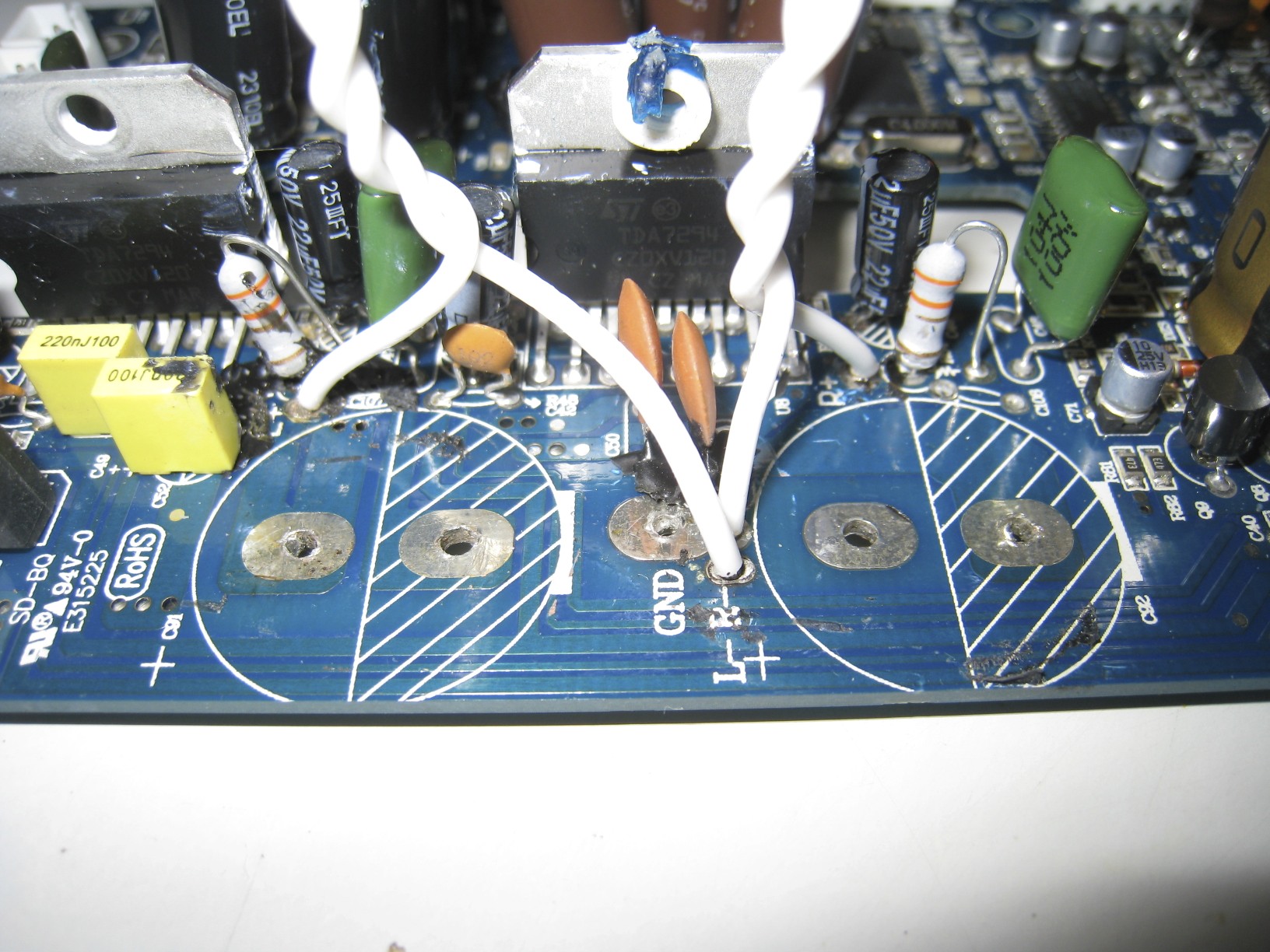
In the picture, you have to invert Regulator and Rectifier. The large IC by the AC plug is essentially a diode bridge rectifier. The two TO-220 packages are DC voltage regulators. Those are probably LM317 and LM337, or 78XX and 79XX.
 
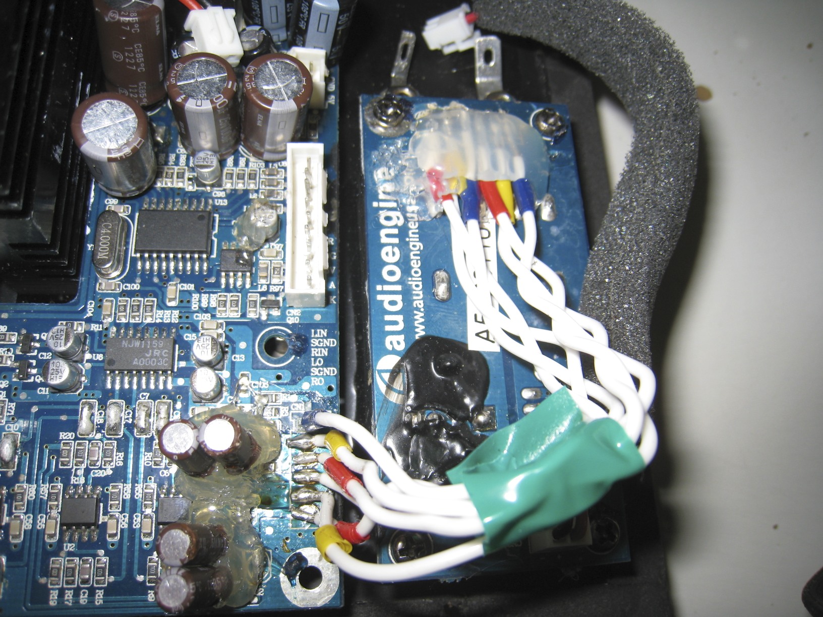
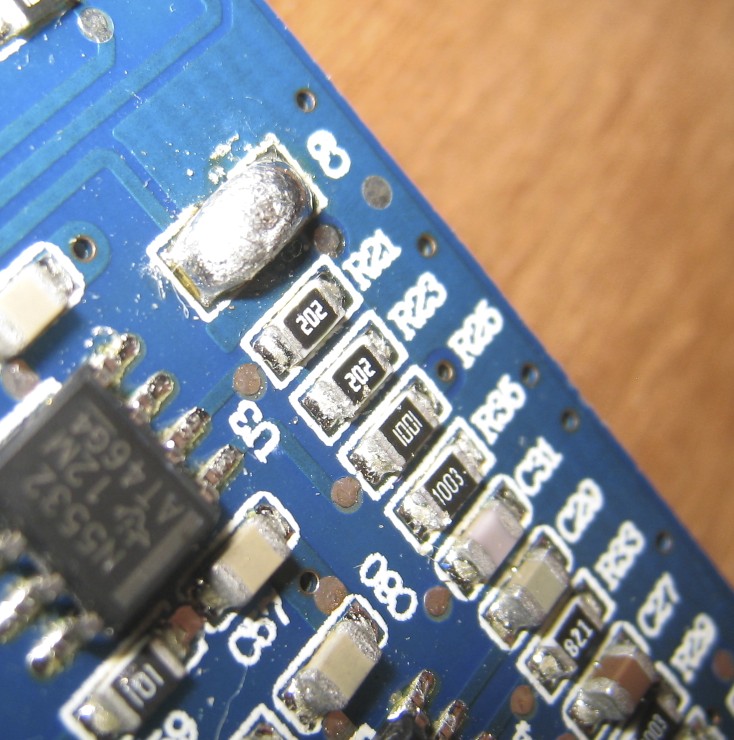
The ceramic capacitors are related to the large ICs connected to the heat sinks. Those are the amplifiers. 
 
This page says the amplifier chips are TDA7294. It also contains information regarding capacitors which may help you.
 
I just read the datasheet for the TDA7294. It doesn't talk about types of capacitors.
 
I searched around the web for what type of capacitors are better for power decoupling in audio application, but there seems to be no consensus. There's just as much hate throw at every types. EIA Class A dielectric seems to be the only "acceptable" type, but those are limited in values. Mouser only stocks one 1 nf but no 0.1 µf.
 
Jan 25, 2013 at 10:54 PM Post #19 of 127
I just noticed you edited your last post. 
size]

 
He took a different approach with his modifications. He studied the input circuitry along with the first stages of amplification, and tried to improve this. Many of the capacitors he changed or simply replaced with a wire were coupling capacitors. The audio signal goes trough those capacitors. They are used to block DC and only allow AC to pass trough. In commercial products, coupling capacitors are used as a safety feature, and not always necessary. Since signal goes trough them, they can degrade the signal quality. Essentially, the less stuff the signal has to go trough, the cleaner it will be.
 
Coupling capacitors create a high-pass filter with the input impedance of the next stage, or with a resistor to ground on their output. Raising their value lowers the corner frequency at which point the filter start to roll off. In other words: Higher value means lower frequency response. Though in practical application, there's a point where raising the value won't give significant gain.
 
If I were you, I'd save my money and leave the ceramic caps in. Their influence on sound quality is insignificant compared to the coupling capacitors. And since there seems to be no clear path to upgrade them, why bother? I'm sure AudioEngine had a reason to use ceramic capacitors. I mean, at this point we don't even know if changing them for another type won't actually be a downgrade.
 
Jan 26, 2013 at 12:51 AM Post #20 of 127
With the MKP2's in hand, i decided to just implement them into the board.
 
Replaced the Polyester/Polypropylene Correction/Decoupling capacitors with MKP2.
Replaced Power Supply Ceramic Disc Decoupling capacitors with MKP2.
 
"Ceramic are more suitable for PS decoupling because of their low parasitic inductance and their high losses, which help to dampen resonances of wiring inductances and the decoupling capacitors."
&
"Due the higher inductivity of the polypropylene, or polystyrene they are not the godd solution for supply decoupling. Ceramic caps has lower impedance over 1MHz, and they succesfully avoid the HF oscillation."
 
However, for this small decoupling purpose, it shouldn't be a large difference. 
Will experiment with other ceramics down the road if i hear any abnormalities with the stacked metal film capacitors.
 
!Updated Section 3 Pictures!
 
Tim
 
Jan 28, 2013 at 4:50 PM Post #21 of 127
Thanks to everyone involved in this thread. I've been curious about modding my A5+ speakers for a while. I'd run across the schematics, etc., on the web that are referenced but I found them to be a bit over my head. I'm somewhat new to this so the step-by-step directions and the really helpful replies have convinced me to try it out. So... thanks and keep it up, I'll be watching!
 
Jan 29, 2013 at 2:14 AM Post #23 of 127
Added one more section for modding.
 
Section 4: Replacing Polymer and Ceramic Capacitors that couples the signal to the amplifier TDA7294 chips.
 
Jan 29, 2013 at 10:26 AM Post #24 of 127
Quote:
If I were you, I'd save my money and leave the ceramic caps in. Their influence on sound quality is insignificant compared to the coupling capacitors. And since there seems to be no clear path to upgrade them, why bother? I'm sure AudioEngine had a reason to use ceramic capacitors. I mean, at this point we don't even know if changing them for another type won't actually be a downgrade.


I just wanted to chip in and say that the larger ceramics as indicated by circles in the earlier pictures are not decoupling caps for the power rails, they are coupling caps for the signals (I had to double check to make sure with a meter for continuity).  That is why they are best bypassed or replaced.  I'm surprised that they used ceramics to couple signal....
 
Jan 29, 2013 at 1:33 PM Post #26 of 127
Quote:
So is there anything wrong on my part for replacing them with MKP2? or would FKP2 do even better since this is for signal coupling.
 
Tim

 
Check the voltage across this cap with the amp powered on, say on a work bench or something with a multi-meter.  If the voltage across this cap (any of the ceramics in that picture, NOT ALL CERAMICS ONBOARD) is just a few milivolts (mV), bypass it with a wire. 
 
My guess is that AudioEngine designed this with a very standard implementation (AC coupled) of a pre-buffer-amplifier, and left in the coupling caps, and when the manufacturer made the unit, they decided to use the same cap EVERYWHERE (like the ceramics and polymers) since batch orders of large numbers is cheaper and it reduces total variety of components (this is far too common, with a good designer designing a good unit, then the manufacturer decides to make substitutions, just ask Centrance on why they INSISTED the manufacturer do not swap the opamps on their famous DACPORT).  They are not really needed because in my experience, the DC on those signal lines are, for all intents and purposes, ZERO.  I measured this on my unit with the amp powered up and playing.
 
Bypassed with no caps at all is better for high-fidelity than ANY CAPS of ANY GRADE.
 
If I had more time with my unit, I would have spent some time to figure out a way to bypass the internal buffer on the NJW volume control chip, since that part is specc'd far below the 5532 opamps, which immediately buffer that volume control chip anyway.
 
EDIT: I see where you placed your MKP and FKP's now (with a picture).  Never mind on shunting them.  I assumed you were placing the MKP's in place of the ceramics in my mod.
 
Jan 29, 2013 at 5:09 PM Post #28 of 127
Quote:
 
 
You're saying i should use a multimeter, test the voltage across the MKP2 along with the ceramics, if they are just a few mV, to bypass it with a jumper wire? Since you already did the measurements, shouldn't i bypass them regardless?
I already upgraded the main capacitors, so i had a feeling the film caps were unnecessary.
 
So, first i'll listen with the film MKP2 caps that i already in the board, after wards, i'll remove all film caps and replace them with a jumper wire.
 
Do i still have the green flag to do my bypass of ceramic smd and polymer bypass under section 4?
 
What is wrong with the internal buffer of the NJW chip and why do you need it bypassed? Would doing that yield some benefits? What would be needed to spec it higher than the 5532's or around the same level?
 
Here is what i have now:


Tim

 
The ceramics you want to bypass are the ones in the bottom part of that picture you took, they are in the signal path.  The ones you replaced with film caps that are red can stay there.  Take a look at the diyaudio thread or the pictures a few posts above, there are two images highlighting which caps are the signal path ones, to improve the sound first. 
 
I measured every one of those caps highlighted/circled in the pictures, and they have practically no DC content while in the signal path, so you are absolutely safe and recommended to take those caps out of the signal path IF YOUR PCB IS IDENTICAL TO MINE, so just to be sure, you should perform your own measurements, we don't know what AudioEngine's engineering tolerances were, but if you have no multimeter, I would say with a high confidence that you are safe to shunt those caps (ONLY THE CAPS SHOWN IN THE PICTURE) with a wire.  You don't need to replace them with anything but a wire, or just shunt them with a wire and leave the component in place.  I recommend using a set of high quality (Silmic II's) for the circled caps in that image at the signal input closest to the jumper connector (white plastic connector with pins in it), so you can be safe against DC from unknown external sources.
 
Jan 29, 2013 at 5:14 PM Post #29 of 127
Quote:

 
Tim, the RED circled caps are the ones you want to bypass with a wire (shunt them), and the blue circled ones replace with some high quality Silmic II's.  Back to back reduces distortion since Silmic's don't come in already made bipolar varieties (so back to back makes your own bipolar).
 
Jan 29, 2013 at 5:48 PM Post #30 of 127
Quote:
 
The ceramics you want to bypass are the ones in the bottom part of that picture you took, they are in the signal path.  The ones you replaced with film caps that are red can stay there.  Take a look at the diyaudio thread or the pictures a few posts above, there are two images highlighting which caps are the signal path ones, to improve the sound first. 
 
I measured every one of those caps highlighted/circled in the pictures, and they have practically no DC content while in the signal path, so you are absolutely safe and recommended to take those caps out of the signal path IF YOUR PCB IS IDENTICAL TO MINE, so just to be sure, you should perform your own measurements, we don't know what AudioEngine's engineering tolerances were, but if you have no multimeter, I would say with a high confidence that you are safe to shunt those caps (ONLY THE CAPS SHOWN IN THE PICTURE) with a wire.  You don't need to replace them with anything but a wire, or just shunt them with a wire and leave the component in place.  I recommend using a set of high quality (Silmic II's) for the circled caps in that image at the signal input closest to the jumper connector (white plastic connector with pins in it), so you can be safe against DC from unknown external sources.


Very detailed, thanks so much.
WIMA told me the Red Film MKP2 will do better than the ceramics that i replaced due to metallized film having self-healing properties and higher reliability/load life.
 
I will shunt the red circles with a wire.
Is there any benefits from removing the ceramics/polymers and  then shunting them, or is there not?
I will be using 6 total Elna Silmic II 22uF 25V.
Four back-to-back for the Input Couplings to Amp.
Two for Input/Output Couplings to Pre-Out.
 
Quote:
 
Tim, the RED circled caps are the ones you want to bypass with a wire (shunt them), and the blue circled ones replace with some high quality Silmic II's.  Back to back reduces distortion since Silmic's don't come in already made bipolar varieties (so back to back makes your own bipolar).

Understood.
 
The guy from the thread is emailing me and assisting me with this mod.
He says to use two capacitors and connect the positive legs together, thus making it a bi-polar capacitor with two negatives.
Just like you, he says the Bipolar will reduce distortion that is induced by the capacitors.
 
Here is a mini map-out of what i will be doing


Either + with +, or - with - should work.  (for making bipolar capacitor from two polar capacitors)
 
By shunting the ceramic/polymers, wouldn't that lower the overall capacitance? Should i have to make it up when using the Elna Silmics?
That is the part in which i do not understand.
 
I will order some Silmic II's today. Is there any other possible mods that you can think of to improve the signal path?
 
Tim
 

Users who are viewing this thread

Back
Top