Here is my documentation on how to modify the tu-05 with a rear 6.3 mm headphone out.
some initial thoughts before you start doing the same modification:
you how to say should know what you can do with electronic parts and what better not:
- bending
- heat resistance when soldering near by
- ...
some basic knowledge is recommended:
- electronic parts and electronics
- how to use a multimeter
- how to desolder and solder
- ...
before starting one should think that something can goes wrong, no success, there is a damage, failure etc:
- ability to debug analog electronics may be needed
for the work and metal work - especially the large hole for the neutrik jack:
- all the tools in place?
- a fine resonant free drilling machine
- a small to tiny electronics soldering iron (not the 100 watt tin can soldering version)
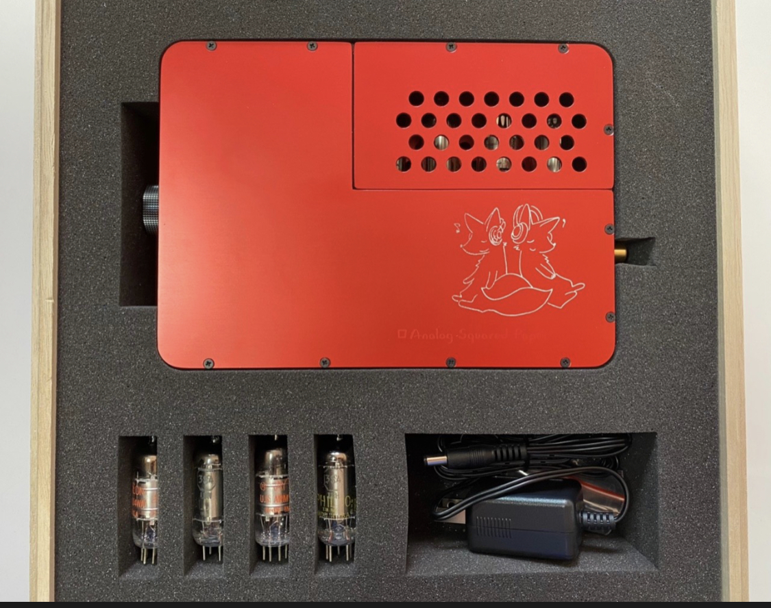
things i used (a maybe not complete list):
- cables, shrink-on tube, tape, pressured air, solder, clips, tool for cable-demanteling, different claws, fine and medium rasps with different shapes, shaping tools, drills for metal, screwdrivers with the exact size, heat gun, digital multimeter, sandpaper, a small brush, vaccum cleaner, 2 litres of coffee, 5 hours, screw clamps to fix the drilling machine on the table, small woodplate, two plates and two wood pieces under the amp while drilling, 6.3mm neutrik jack, 2nd as reserve, superglue or screws for the neutrik jack, knife, toothpicker, pieces of cardboard, ...
if you have decided to do this modification:
- always use a brush, pressured air and a vacuum cleaner to after each step remove all (and be absolutely sure that there are NO) aluminium parts, particles and dust left.
- check everything, charging, channels left right correct, two headphones at the same time, charging while listening, ...
so much fun doing the same modification .....
Preparing the amp:
- check that power switch is in the off-position
FIRST STEP:
- remove the tubes
- remove the part of the housing around the tubes (screws on both sides)
SECOND STEP:
- open the case (removing the screws) on the side opposite to the side where the switches are:
removing the battery:
TAKE GREAT CARE NOT TO SHORTEN THE CONTACTS OF THE BATTERY!
- put the batttery out of the amp
- use a soldering iron to desolder the two wires of the battery
the battery is connected to the power switch here (blue arrow):
here you see the two wires desoldered:
isolate the wires (both, one after the other, then put them together) with some tape:
- place the battery somewhere else until again needed to be reconnected.
removing the power jack:
the cables of the power jack are soldered at the same pins the battery wires were (green arrow, desoldered wires of the power jack - blue arrows):
- desolder them
- remove the screw-nut
- the power jack now can be removed:
- i put the screw-nut over the cable again not to loose the nut
- i measured the size of the hole the power jack was inserted toknow the diameter when drilling the new front hole:
preparing the amp for the next steps:
- remove the foam rubber that was placed under the battery:
- remove all the screws of the side-panel (but not the screws of the switches, only the screws holding side panel and frame together:
- carefully rotate and place the amp as shown:
- remove the screws holding the frame and the tube panel together (blue arrows)
- unplug the connection cable between the two pcb's on the side as shown (connector and cable - green arrows)
- detailed view (connector and cable - green arrows):
installing the power jack in its new front position:
first of all a new hole on the front panel is needed:
- i driiled a hole with a 3mm drill for metal firstly, as symmetrical as possible above the input jack, somewhat limited by not coming to near to the potentiometer
- i then used a 7mm drill to get the hole larger
- i then used a small rasp to get the hole to the 8mm diameter size.
to drill the hole while protecting the amp:
- i placed the amp on two plates (concrete and wood), so that the volume knob is not pressed onto the table (blue arrow)
- i used a piece of cardboard between amp and driil to protect the amp from all the aluminium particles flying around while drilling (green arrow)
top view:
now you can assemble the power jack in its new front position (blue arrow) and fix it with the screw-nut:
preparing the hole for the rear neutrik 6.3mm jack:
i placed an adhesive felt disk of slighty smaller diameter than the hole needed exactly (and i mean really exactly, here each mm counts) in the position the neutrik jack has to be placed (blue arrows pointing to the center):
to protect the amp while drilling:
- cover the electronic pcb's and the tube sockets (I FORGOT THIS) with strong tape (blue arrows)
- reassemble the screws of the side panel (green arrows) not to bend the frame when drilling with some preassure on the frame
i had no better tools so to get a large hole:
- i drilled a lot of small holes around the felt disk (blue arrow)
- then the same with a slightly larger drill
- you can see the volume knob placed between the two plates (green arrow)
top view:
- i then removed the aluminium in the middle using a small round rasp cutting from small hole to small hole and a larger rasp and a shaping tool to get the large hole (nearly) round (blue arrow):
partly reassembling the amp for the next steps:
i used the same pictures as taken during disassembling, so the new larger hole for the neutrik jack can not be seen:
- reconnect the cable and plug it into the connector (green arrows)
- reassemble frame and tube panel using the same screws as before (blue arrows)
cable and connector (detailed view, green arrows):
- put the foam rubber piece that was placed under the batttery back to its former position:
- reassemble the screws between side panel (the one with the switches) and the frame (blue arrows):
- reassemble the frame part around and protecting the tubes
reassembling battery and power jack:
i used the pictures taken while desoldering so the positioning of the cable from the left now has obviously changed and should be from the right side:
- (re)solder the power jack cable (blue arrows) with the power switch pins (green arrow) where they were soldered before:
TAKE GREAT CARE - BLACK to BLACK, RED to RED:
- CAREFULLY REMOVE THE TAPE FROM THE BATTERY WIRES
- TAKE GREAT CARE NOT TO SHORTEN THE BATTERY
- (re)solder the battery wires with the power switch pins at the same position as the power jack cables (blue arrow):
the amp now should look like this:
assembling the additional cables for the rear headphone out and the neutrik 6.3mm jack:
the new cables for left, right, ground can be directly soldered to the output transformers on top of the exsiting cables for the front 3.5mm headphoe out jack:
LEFT - white arrow
RIGHT - red arrow
GROUND - black arrow
i used cutted pieces of an beyerdynamic t5p headphone cable (inner wire and shield/ground on each cable soldered together) and bundled them together using white shrink-on tube (blue arrows).
- take care that the cables are long enough to solder and assemble the neutrik jack (second blue arrow):
- don't forget to put the cable through the hole first
- solder the pins with the corresponding pins of the neutrik jack
i tested the neutrik jack by plugging in a headphone first and then measured the position of left, right, ground pin by applying a music signal and listening and measuring the resistance with the multimeter before:
LEFT - white arrow
RIGHT - red arrow
GROUND - black arrow
Soldered pins: blue arrows
befores assembling the neutrik 6.3mm jack:
- CAREFULLY isolate the pcb above with tape (blue arrows)
- CAREFULLY bend the connection cable between the to pcb's so that it is flat positioned under the jack (green arrows)
now the amp should look like this:
i had no screws, so i used superglue to fix the neutrik jack in its position.
amp completely assembled (open case):
this is the now finally modded amp (rear view):
this is the now finally modded amp (front view):
amp completely assembled (closed case) - and case closed:
this is the now finally modded amp (front view):
this is the now finally modded amp (rear view):
as final action some workbench cleaning is recommended:
Very very interesting GG. I am tempted to do the same.
But... are we sure that there is no disaventage to increase so much the lengh of the cable going to the headphone Jack ? it is very short when the jack is on the front ? isn't it ?
Can you describe again the cable you are using for the internal rewiring. I think that it is an important reason for the improved sound.
as long as your headphone cable is 1 to 1.5 meters, the internal length is not of importance. your headphone adapter cable may have the same length.
as posted the internal cables are cutted pieces of the t5p cable, this is all i know about it.
i will replace the cable with high purity lcofc grado cables later - 4 wires for both left and right, 8 wires for ground (current flow over the ground cable is the sum of left and right, so always higher).
GG you are right, I forgot that there is at least 1 to 2 meters of cable between the TU-05 and the headphone cups, so.... + 10 cm internal wiring will not make a big change. Good point ! I think I will also make this 1/4 change like you. I just need to decide from the start which cable I will use internaly to replace the stock cables.
on another subject: I need to find a very good CLOSED headphone that DO NOT LEAK sound outside for when I listen in the bed...close to my wife. Obviously my TH-900 leaks too much sound...
Any suggestion for the BEST non leaking cam (best sound + least leak) to go with our TU-05 ?
I have in mind for example : Beyerdynamic T5p, Edition 8 , Signature PRO... ?
T5P without a shadow of a doubt. Zero leakage externally for anyone near you and I find excellent seal for the listener as well.
Be aware with this headphone that it needs a good 300 hours on it to fully settle in and experience deeper bass. It is a wonderful match for the TU-05. I could not recommend it more highly!
just finalized my tu-05 twin output mod photo tutorial (thanks to ianmedium, who asked for doing this when i posted the idea!), wow, this was the largest post i ever made!
T5P without a shadow of a doubt. Zero leakage externally for anyone near you and I find excellent seal for the listener as well.
Be aware with this headphone that it needs a good 300 hours on it to fully settle in and experience deeper bass. It is a wonderful match for the TU-05. I could not recommend it more highly!
Testing now Telefunken DF904 / Philips DL92, and it is my prefered combo... so far (Very good bass...).
Then comes the Combi that came with the TU05 : Raytheron 3S4 / RCA 1U4 ( 2nd best...for me)
And, I have also tested 4 other combos, but without good results (according to MY ears): Sylvania 3S4 / Tungsram 14T4
Mullard 3S4 / Tungsram 14T4
Mullard 3S4 / Siemens 1T4
Telefunken DF904 / 1L33.
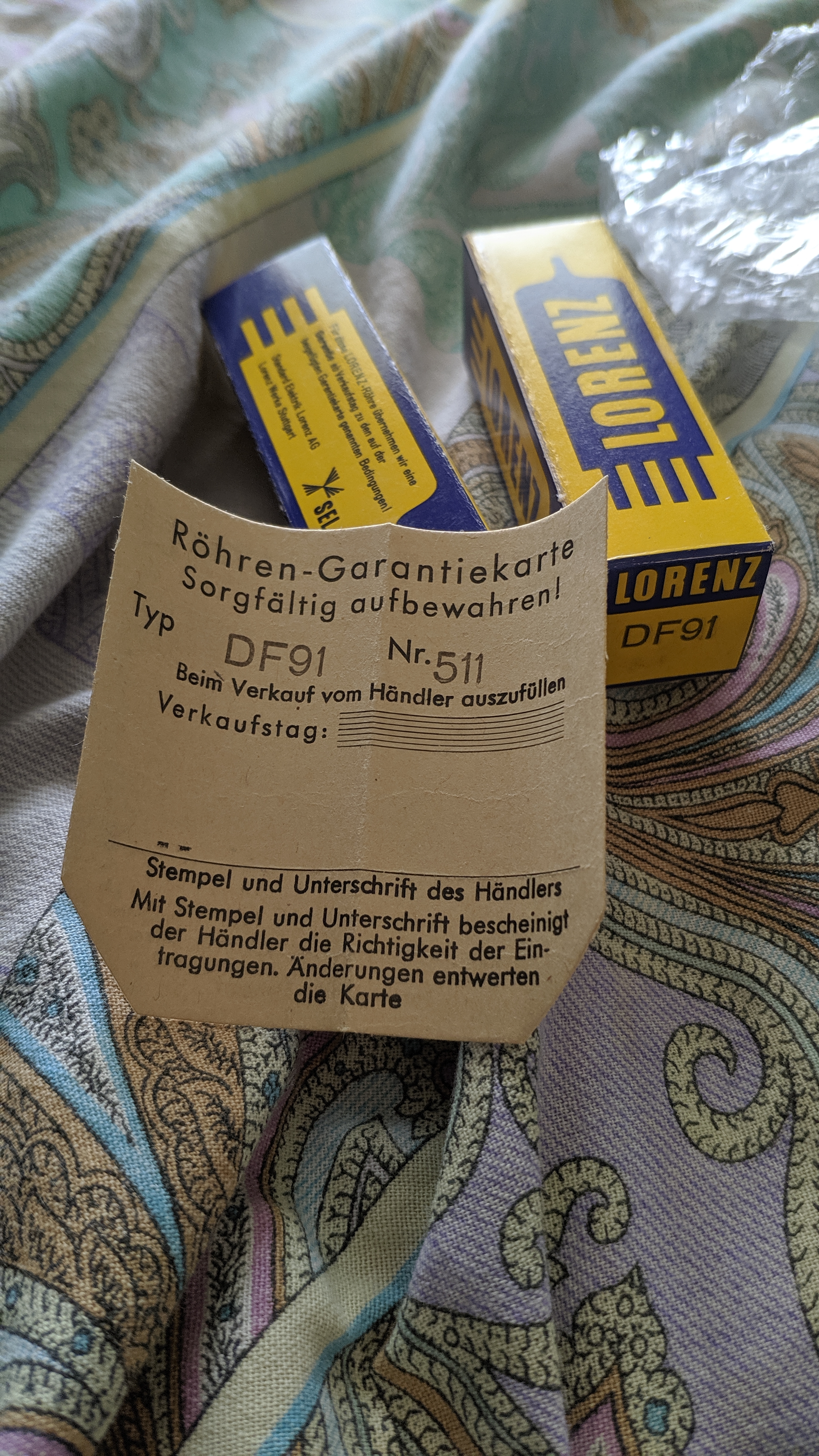
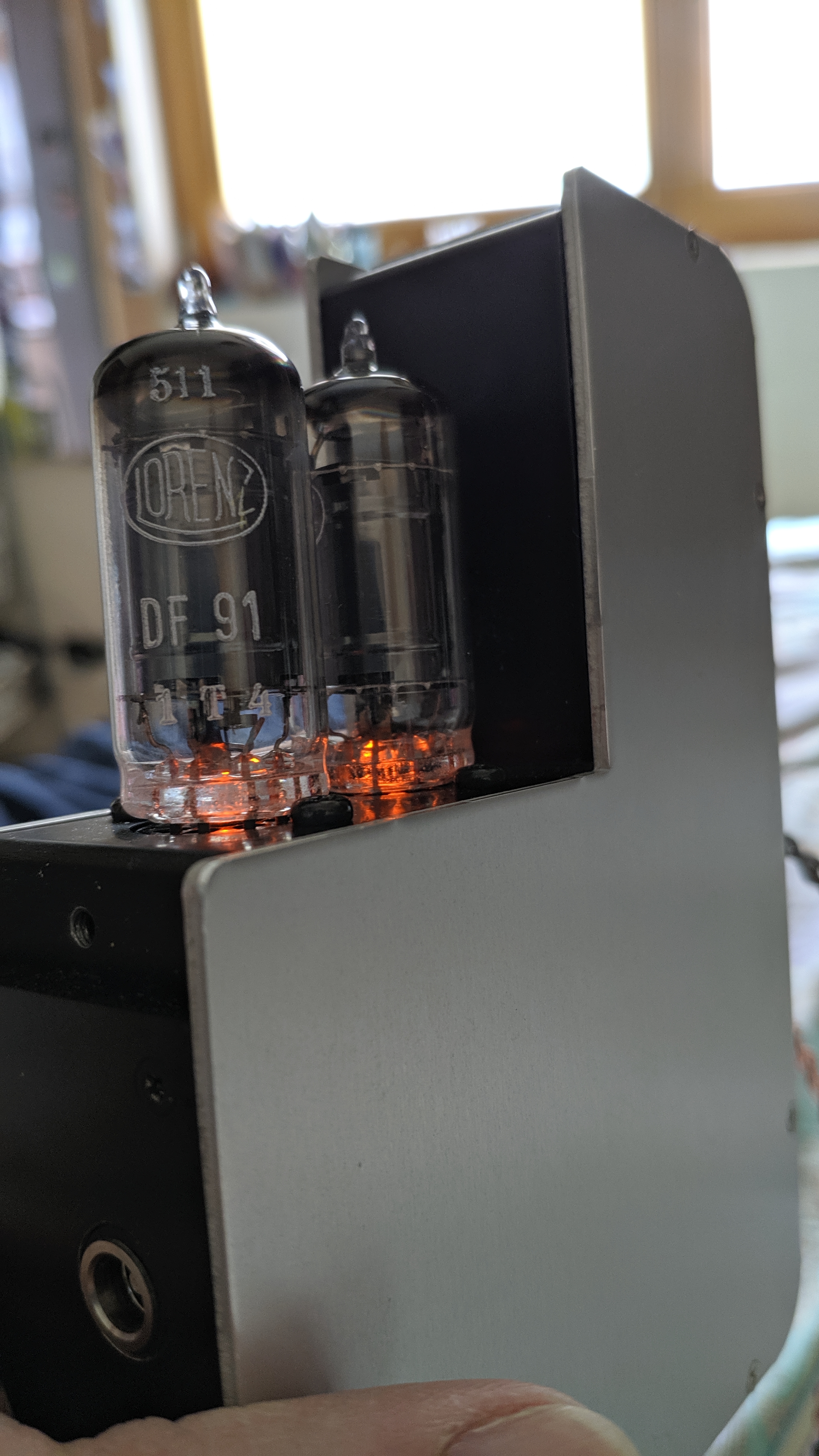
Here is bellow the list of the tubes that I Owe.
Power stage (3S4, DL92, CV820, N17, 1L33...) Voltage Stage (DF91, DF96, DF904, 1U4/1T4/1T4T, DT153, W17...)
*************** ********************
Sylvania 3S4 (US Army-1945 !) Tunsgram 1T4T
Mullard 3S4 (1959) Siemens DF91/1T4
Siemens DL/92 3S4 Telefunken df904/1U4
philips dl 92/3S4 RCA 1U4 (orange printing)
tung-sol ken rad dl92 ( US Army-1950)
Tesla 1L33 And...2 Lorenz DF96 that are unfortunately of the same type
--> I really Need to find 2 similarLorenz DF96
Raytheron 3S4 to built GG's "dream combo" Lorenz df96 + Tung-sol ken rad dl92 (+ also Mullards DF91 + Tung-sol ken rad dl92)
-- > Please based on this list, could you suggest other combinaison worth testing.
--> And also what other tube I should really try to get (Lorenz DF91 ?? Mullards DF91 ? lorenz dl92 + valvo df91 red label ?)
QUESTION: sometimes, I have a lot of background parasit sound. I just have to turn the TU-05 OFF and ON again and.... gone the parasite sound ?? Someone know what it is ??
And: HERE SOME NICE FREE JAZZ DOWNLOAD : I love " How Deep Is The Ocean " and "Griff "
(they offer many versions of the same 2 songs. This is ment to show the differences betweens several Turnable cartridge. I have to admit I can't hear real differences. Can you ?
regarding your background parasite sound - the only thing i can think of would be the charger / battery circuit or a power regulating stage because these are the only other parts that could run into auto-resonance.
if it sounds like pfffffffffffffffffff pft ........ pffffffffffffffffffffff rt .....chhhhhhhhhhhhh bft chhhhhhh pffffffffft ..
it could be a broken capacitor, but then usually only one channel if part of the amplification stages.
Bmichels, with the noise, also try gently tapping the tubes to ascertain it is simply not noisy tubes! I find with noisy tubes if one gently taps the tube with a finger nail the noise can temporarily go. If this is the case it's probably a bad tube. I had that with one of the Telefunken 1U4's I recently got which is really annoying as I loved the sound of them so am now hunting another 1U4 to replace it with!
This site uses cookies to help personalise content, tailor your experience and to keep you logged in if you register.
By continuing to use this site, you are consenting to our use of cookies.


") (Very good bass...).
(Very good bass...). 


