V-dac modifications
Jul 8, 2009 at 7:06 PM Post #46 of 259
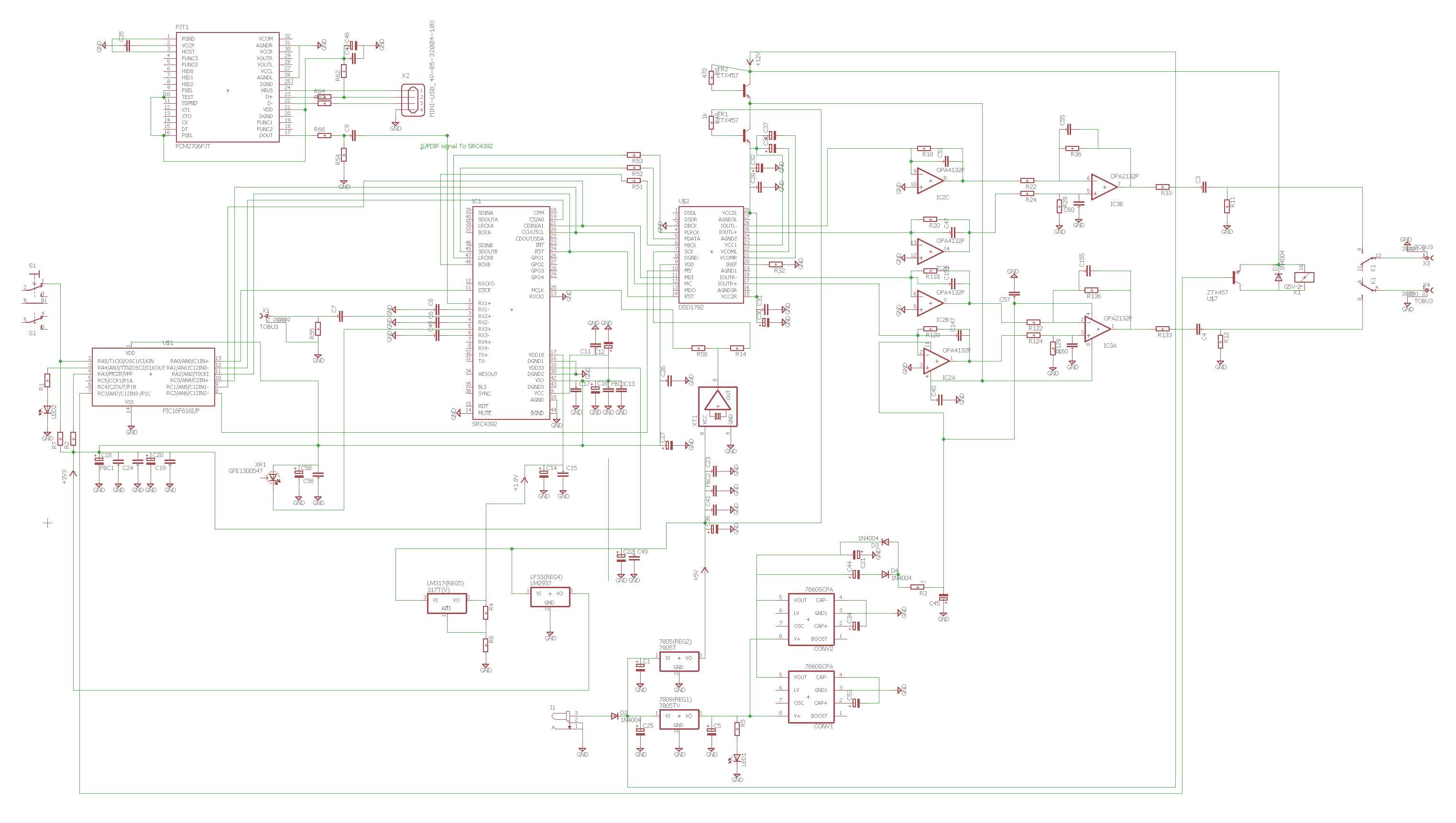
Hello all: I've just received my V-DAC, and I've been following this thread. One mistake that's being made is that C's 55, 60, 155 and 160 are definitely 220 pF, NOT 22 pf. Just to be sure, I pulled one out and measured it. Dutchamps got it right in a previous post.
If you go to the TI website and search for the DSD1792 datasheet, you'll see their recommended design for the I to V and the output stages (they call them measurement circuits). If you calculate the rolloffs for the V-DAC, you come up with 86.8 KHz for the I to V and 185 KHz for the output, which is very close to the reference design. If you use 22 pF caps, you have a rolloff 10 times higher (1.8 MHz). This will let a lot of trash through the output and is probably why things don't sound right. If you can order from Digikey in the USA, their Panasonic P series polypropylene caps are excellent replacements for the 220 pF's as well as the 3900 pF's. The only drawback is that they have a $25 minimum order.
A question: for those using the 4562 for the output: has anyone measured the dc offset? If it's significantly less than 1 mV, you can almost certainly replace the output caps (C 3 and 4) with jumpers.
Thanks in advance.
 
Jul 9, 2009 at 12:47 PM Post #47 of 259
I changed out C160, C155, C55, C60 to 220pF Polypropylene and sound did improve sightly. However the improvement in sound could also be partly due to change in material from Polystyrene to Polypropylene. The improvement in sound is slight but still can be distinguished easily. Thanks to Dutchamps and sluggoaudio for pointing out my mistake.

I also replaced the resistor R11 and R12 at the same original values for a better one and that helped to lower the noise level and clean up the sound a little tiny weeny bit.

As mentioned previously, certain tracks does not sound right and i think the main factors could be the inappropriate capacitor values that I have changed rather than due to the 22pF. But this is just my guess.

I think using 'exotic' capacitors such as Silmic II and Nichicon Muse KZ has helped to 'amplify' the differences. Now I understand why it is commented that changing all caps to 'exotic' may not necessary yield an improvement to the sound.

Some of my bond pads have started to lift up due to my repeated trials and error of soldering/de-soldering caps. I am satisfied with the sound right now with this configuration and its time to sit back and enjoy. I have spent too much time in experimenting. In addition, I read that Silmic II needs 100hours to break in! I hope the vdac will sound better as it gets more burn in.

My updated modification list:
C25 : Panasonic FC 1000uF 25V
C21,C44: SE 100uF 16V (S.E.66)
C5,C53,C34,C39: Panasonic FC 100uF 50V
C14: ELNA Simlic II 10uF 50V
C52, C61: Panasonic FC 100uV 50V
C45, C22 : ELNA Silmic II 100uF 63V
C3, C4: ELNA Silmic II 10uF 50V parallel with Nichicon Kz 10uF 50V [Original 47uF]
C43, C46: ELNA Simlic II 1uF 50V
C20, C58 : ELNA Simlic II 10uF 50V
C16, C12, C29, C36,C18: Nichicon KZ 10uF 50V
C27: ELNA Simlic II 10uF 50V
C31, C28: Non-elco 100,000pF (Polypropylene) [Original 104M]
C10: Panasonic FC 100uF 50V [Original 104M]
C30, C32: ELNA Simlic II 10uF 50V
C38, C37: Nichicon Muse KZ 10uF 50V
IC5:LME49740NA [Original MC33079]
IC7: LME49860NA [Original NE5532]
C147, C151, C51, C47: Non-elco 3900pF 630V (Polypropylene)
C160, C155, C55, C60: Non-elco 220pF 630V (Polypropylene)
C40, C57: Non-elco 100,000pF (Polypropylene) [Original 104M]
C2, C1: Non-elco 1,000pF (Polypropylene)
C11, C24, C26, C23: Non-elco 100,000pF (Polypropylene) [Original 104M]
C49: Non-elco 1,000pF (Polypropylene) [Original 104M]
R11, R12: 10k Ohm resistor
 
Jul 9, 2009 at 12:53 PM Post #48 of 259
I am using LME49860 which specs wise I think is pretty much the same or close to LM4562 although I did not check to compare them.

I did measure the dc offset previously and they are definitely not below 1mV and not to be bypassed. Let me know if you have a way to reduce the dc offset such that the output caps can be bypassed with no degradation in sound quality.
 
Jul 9, 2009 at 6:03 PM Post #49 of 259
sluggoaudio

Can you convince Spore.
Hes using electrolite caps ELNA Silmic II 10uF 50V for C3 and C4 with the polypropulene types the sound must be much richer and more detailed sound stage.
It is a day and night difference.
biggrin.gif

Another ....
I have a question the dc offset, how do i messure it?
dc multymeter at the output? looks dangerous to me course of the internal tention of 3-9 volts of my fluke multymeter.
Did you messured it by a scoop?
And what can you tell me about my chosen OP270FZ type of opamp instead of the 5532DD?
Spore
Hihihi i was right all the way, np m8 everybody makes mistakes.
Another thing is:
Polystyrene sounds more detailed (sometime too much)then the Polypropylene ones.

in the past i have seen a artical of caps and behavior in sounds transport through a cap.
Came out from best til worse.

Polystyrene (in some cases, mostly fitering jobs)
Polyropylene
polycarbonate
Electrolite (+/- polarity depending)
Electrolite (non polarity, bipolair)
tantal
ceramic s (but very good in filtering VHF, and there is a lot of it in the V-dac)
Thats why i left them round the digital part of the DAC ;D


Re-solder every part is a must that makes a lot clear, must be the bad solder quality.
I have placed the pcb board in to another case.
I removed the usb and switch, i shall never use it.
So the dac will let see the two leds through the front.
i placed the dig input at the rear of the case next to two single output connectors
(i dont use the plastic on placed on the pcb)

Dutchamps ;D
 
Jul 9, 2009 at 8:21 PM Post #50 of 259
Dutch,
To measure DC out just put the tester in DC mV and measure from ground to each channel live... no worries. When I tried some opamps on the output place, I always found some mV of DC offset.
How are you doing with the nice(r) PSU?
Regards,
Josep
 
Jul 9, 2009 at 9:48 PM Post #51 of 259
Dutchamps,

Thanks for the advice. It is well documented that Polypropylene at C3 and C4 will give much better results and I do agree with you. The thing that is pulling me back is that to fit the more popular and better ones inside, it is too big and a challenge to fit inside the original vdac case.

I remembered I was using 3900pF Polystyrene initially and later switched to Polypropylene. I preferred the Polypropylene sound although I was running the wrong values of 22pF Polystyrene. It a pity we are living in different parts of the world else we could arrange a time and place to listen to how different config sounds like
smily_headphones1.gif
 
Jul 10, 2009 at 3:45 AM Post #52 of 259
Well i did comply with the polypropylene ones into the Vdac casing.
But it takes a lot of skills to do it, and some cases dangerous damageing the pcb board.
Never mentioned, but without casing, just the pcb board on a piece of isolated sheet operating sounds much more detailed.
It provides a much richer defination of where the sounds comming from.
I think it has all to do with the VHF that messes up the pinpointing, im thinking about a synthetic casing.

Messuring the opamp ... understude , thx

How are you doing with the nice(r) PSU?
Im depending on my audio supply shop of DIY.
So this will take some time
And "the allways money isues"
biggrin.gif


Messured the dc offset its very low, about 1mv or less, but need a little cap to get the bass good enough.

will be continued
biggrin.gif
 
Jul 15, 2009 at 7:11 AM Post #53 of 259
Hey all: I finished a regulated 12V supply for the V-Dac tonight, and it appears to be functioning nicely. One thing I noticed is that the wall wart that comes with the V-Dac is completely unregulated, measuring 16.5V with no load. I haven't played with it much, but that can't be good. One of the things that really bugged me is that the DC connector for the V-Dac is a strange one that I couldn't find, so I just ended up chopping the cable off the wall wart to use in my supply.
I built a pretty conventional supply, but with quality components: the rectifiers are ultra fast recovery, and the regulator itself is a LT1085 which is a step up from the LM317 that's normally used. The adjust pin bypass cap is a Nichicon Gold, but otherwise, there's nothing special. I hope that by providing quieter, stable DC to the V-Dac, I won't have to replace all of the supply bypasses (the majority of the mods that are being done here), and instead I can focus on the output stage.
By the way, the pc board is a stock Vellemann 1A DC supply: there's a few things under the board that you can't see, but nothing special secret: 2 diodes to protect the supply in case of a short on the output and an extra resistor on the adjust pin (and pot) to limit the adjust range from 10.5V to 12.5V.
The terminal strip resistor is for a LED (hard to see) and the green jumper is in case I had a ground loop between the AC ground and the V-Dac ground: luckily, I didn't need to cut it (it's dead quiet): I'm using the optical input, so ground loops shouldn't be an issue, but I wanted to be sure, just in case.
Total cost is about $50 and an afternoon of work.
 
Jul 16, 2009 at 3:35 PM Post #54 of 259
what a beauty sluggoaudio good work on that power section
Do you have the velleman number of pcb (kit)
Its a 1,3 mm thick connector its listed in your manual (little paper)

Can you send me a schematic to compare with mine to come ....

what do you hear on the great power supply instead of the old adaptor (sucks in
k701smile.gif
)


Greets Martin
 
Jul 16, 2009 at 10:14 PM Post #55 of 259
Hey Dutchamps: The Velleman kit is k1823: I'm getting them from partsexpress.com in the USA. This one has 2 mounting holes and the regulator provides the 3rd mounting point. They have a newer kit with a board that has 4 holes on it and a different layout, but I don't like it as much as this one.
I wish they'd just pick a 12V plug worldwide and stick to it. These things are so hard to find. Normally, I'd use a XLR microphone connector, but there's no space to mount one on the V-Dac without butchering it.
The sound? Uh, it doesn't sound any worse! I'm still waiting for my op amps from National Semiconductor so I can do my V-Dac mods. Then I'll sit down and do some listening. I'll keep you posted. I'll draw out a schematic later. It's pretty much a stock design, just with a few nice parts.
 
Jul 19, 2009 at 7:45 AM Post #57 of 259
Looks very good ajustable voltage nice work.
Maybe i use your drawing .... but dont use the tantalium cap they are realy bad.:d
Sinds i allready have say goodbye to the V-Dac casing it isnt difficult to connect the psb to the v-dac course psb and v-dac print are in the same case.

Velleman is very easy here its a product of Belgium and easy to get.
Thanks for the info sluggoaudio
beerchug.gif
 
Jul 19, 2009 at 8:23 AM Post #58 of 259
Some time ago my opinion was that there was a point were more mods to the V-DAC was 'too much'.
I have actually moved that point: this little wonderfully DAC may be found for 120ukp (under 150 euro) in UK and as Dutchcamps point out there is no 'obligation' to use its original case, not to mention the crappy PSU. We can have a new full-size box for euro 50, and we can make a simple but clean linear PSU with +-12V (analog rails) and +5V (digital rail) for another euro 50 (or less). It is really easy for someone able to hold a soldering iron from the right side to do this (and see were on the V-DAC board the PSU cables must go).
For a total cost of under 250 euro (this is what a DacMagic costs in UK, btw) and some afternoon's (just a couple) work, I think the end result will be a very good unit with still room for improvement (new opamps, better caps). The next step will be use a passive IV out (lundahl transformers), but this alone is around 200 euro... We will be still under around euro 500 however, I do not see much alternatives able to be at this performance level for this price (or maybe double it).
Regards
Josep
 
Jul 21, 2009 at 3:26 PM Post #59 of 259
GOODBYE V-DAC casing
biggrin.gif


Have made the V-dac in another casing like i said earlier.


Still waiting for the psu will be get on this comming saturday.
You see the original power connector that will be gone if psu is ready.
Also removed usb and switch, relocated the dig.input to the back side.
For all users DONT EVER USE the lowsy optical input this sounds much worse then the 75 ohm coaxial input. especialy this note for sluggoaudio
tongue.gif

Groundloops only appair when you connect two earths.
So use the dig.input earth for the audio output, then your sure.
Use a quality cable course it makes a lot of difference.


forum doesnt accept my pics
They are located here
foto vdac album | Sof2-penguin | Fotki.com
picture DSCN2372 and DSCN2373
 
Jul 22, 2009 at 2:33 AM Post #60 of 259
Hey everyone: here's my take on the mods to the V-Dac itself. First of all, I have no problems with the optical input. My computer's motherboard does have a spdif header that I'd have to connect to a 75 ohm rca; that's a project for another day. The elimination of ground loops via the optical input is not a trivial benefit.
So, what I did was to replace all of the signal caps (4x 3900pF, 4x 220pf and 2x 1000pf) in the analog side with Panasonic polypropylenes, the quad opamp was replaced with a NSC 49740, the dual opamp was replaced by a pair of Burr Brown 627BP's (the low noise version), and I removed and jumpered the output caps and removed their 10K drain resistors. The big jumper near R11 in the picture is just a convenient ground for test leads.
I found a very nice dip adapter for the 627's from Cimarron Technology, Inc. They make lots of neat ic adapters for modding.
The DC offset on the outputs is .4mV for one channel and .1mv (the limit for my meter) on the other. I suspect I could improve this by using tightly matched resistors around the 49740, but this thing feeds a 100K passive volume pot and I can't hear any noise when I turn the pot, so the offset is low enough to dispense with the caps.
Here's a new one: another mod that you can't see is are a pair of current regulator diodes (1N5303: 1.6 mA) mounted on the bottom from the negative supply to each output to bias the 627's into class A (cathode to pin 4, anode to the output after the 75 ohm resistor). All in all, it sounds quite nice, and as best as I can remember, it has more punch and detail than the stock unit.
Tantalum caps are ok when used properly: they have excellent high frequency characteristics and are included only to stabilize my regulator's output when using a fairly long (4 feet) cable to the V-DAC.
Also, I think it's a good idea to wash your V-DAC with 99% isopropyl alcohol: the stock unit had a lot of flux residue on it.
Another thing about tantalum caps: old (and very valuable) Neve recording modules are full of them in the signal path; if you swap in new electrolytics, you will change the sound and effectively ruin the module; sometimes distortion can be a good thing.
Anyway, this has been a fun journey; I await your comments. Thanks.
 

Users who are viewing this thread

Back
Top