


DBaldock9
Headphoneus Supremus
That's a really nice soldering kit. I dabbled in surface mount soldering years ago modding video equipment. I wouldn't know where to start with audio. I've sold all of my tools over the years. A good fluorescent lighted magnifier is worth it's weight in gold I can tell you that. As well as a good solder sucker.
I've got one of these magnifiers, with LED lights. I bought it, to help my Mom see better to read, back in 2016. After she passed away, my Dad told me to take it, to help with my hobbies.
https://smile.amazon.com/gp/product/B019R1A8HW/
I also have a magnifying visor, like this one -
https://www.vellemanusa.com/products/view/?country=us&lang=enu&id=351145
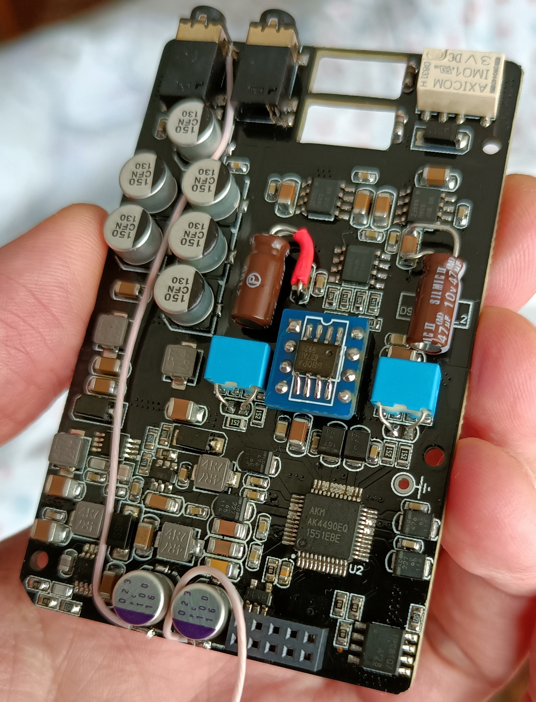
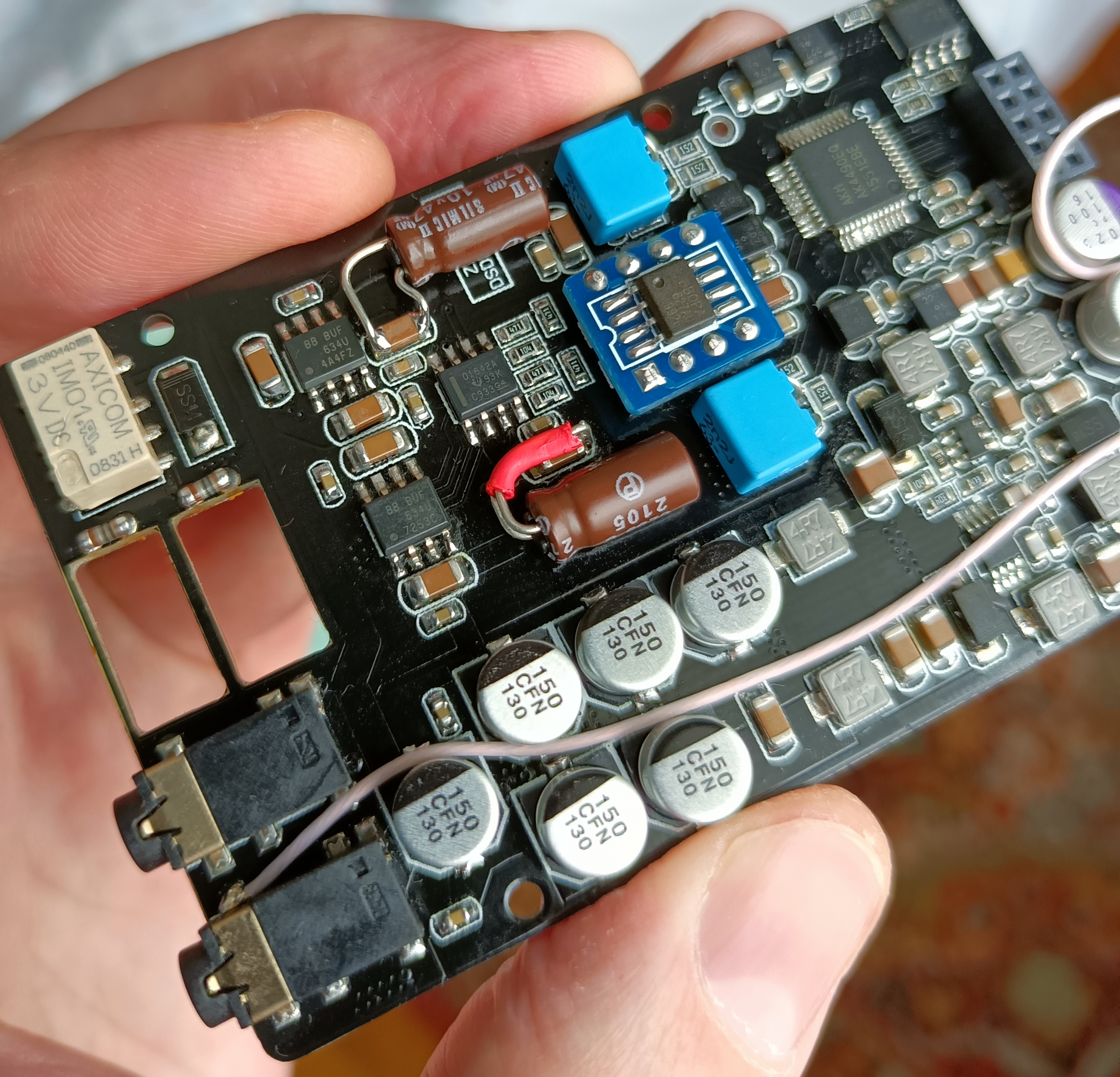
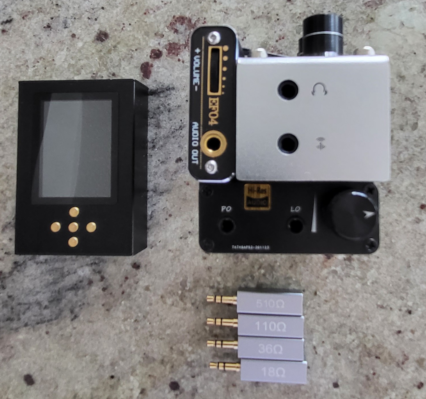
Now that my new soldering equipment is arriving, I'm going to be doing some more mods on my DSD.