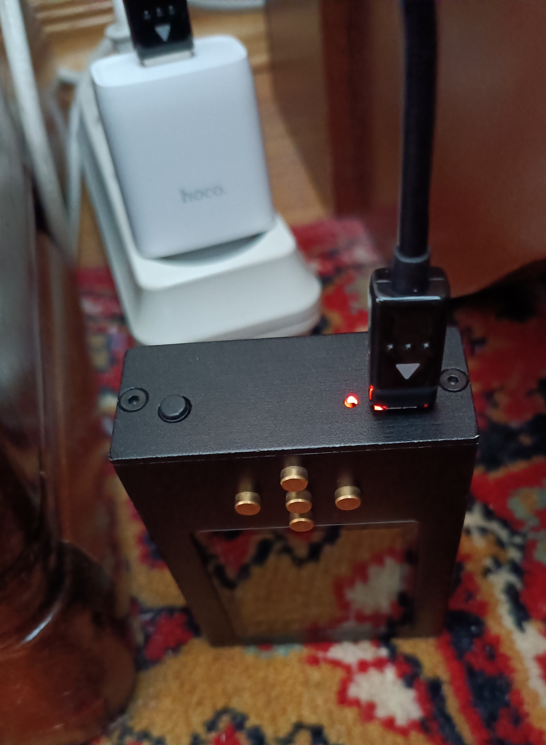
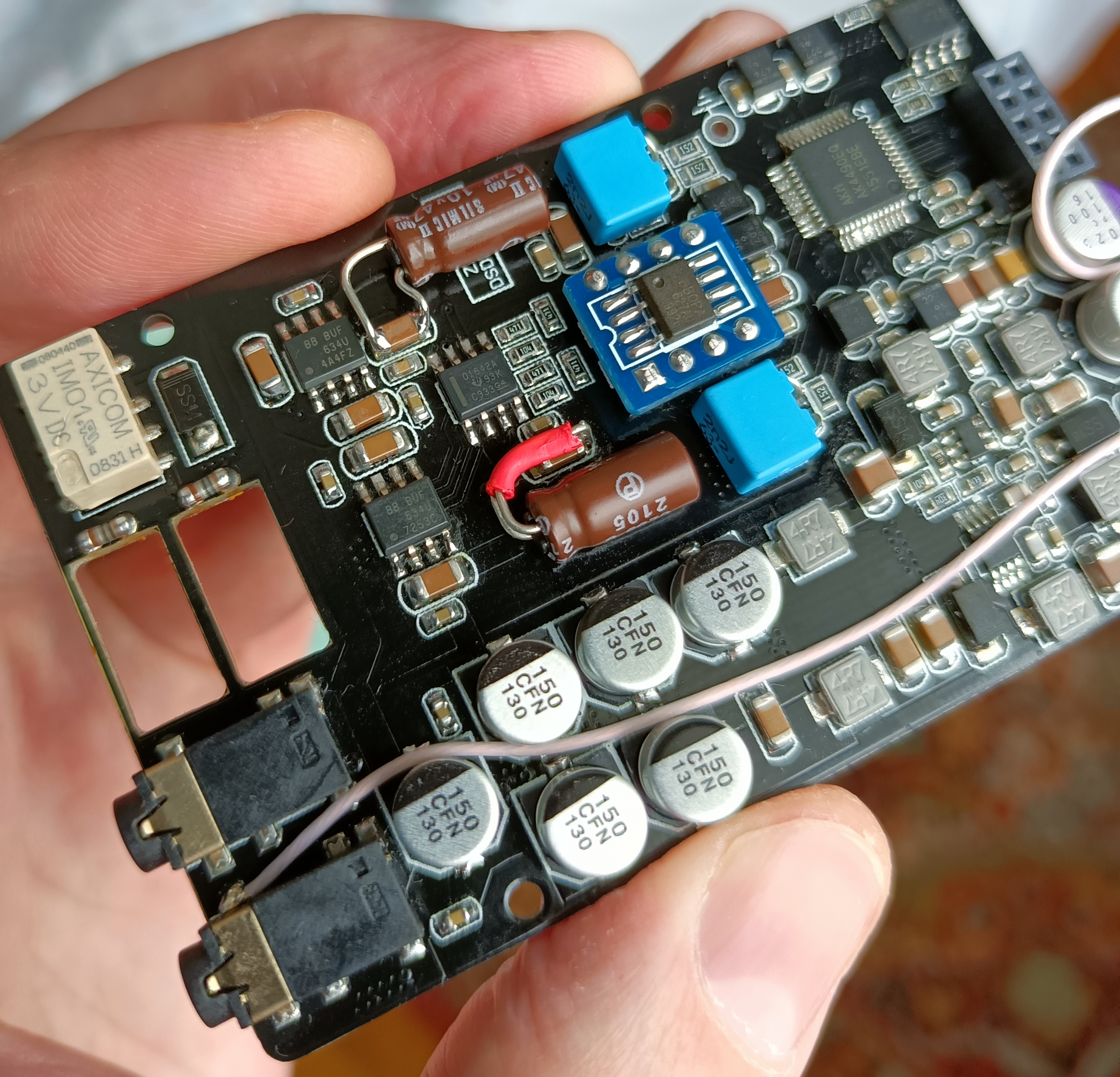
hello guys, I need some help. I've got a Burson V6 from Burson for a test. I also got the extension wires. I've got it working, but I want to put the boards back in the metal casing.


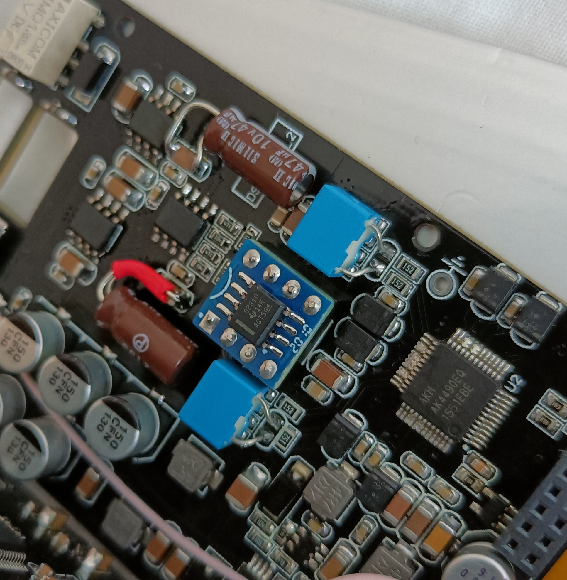
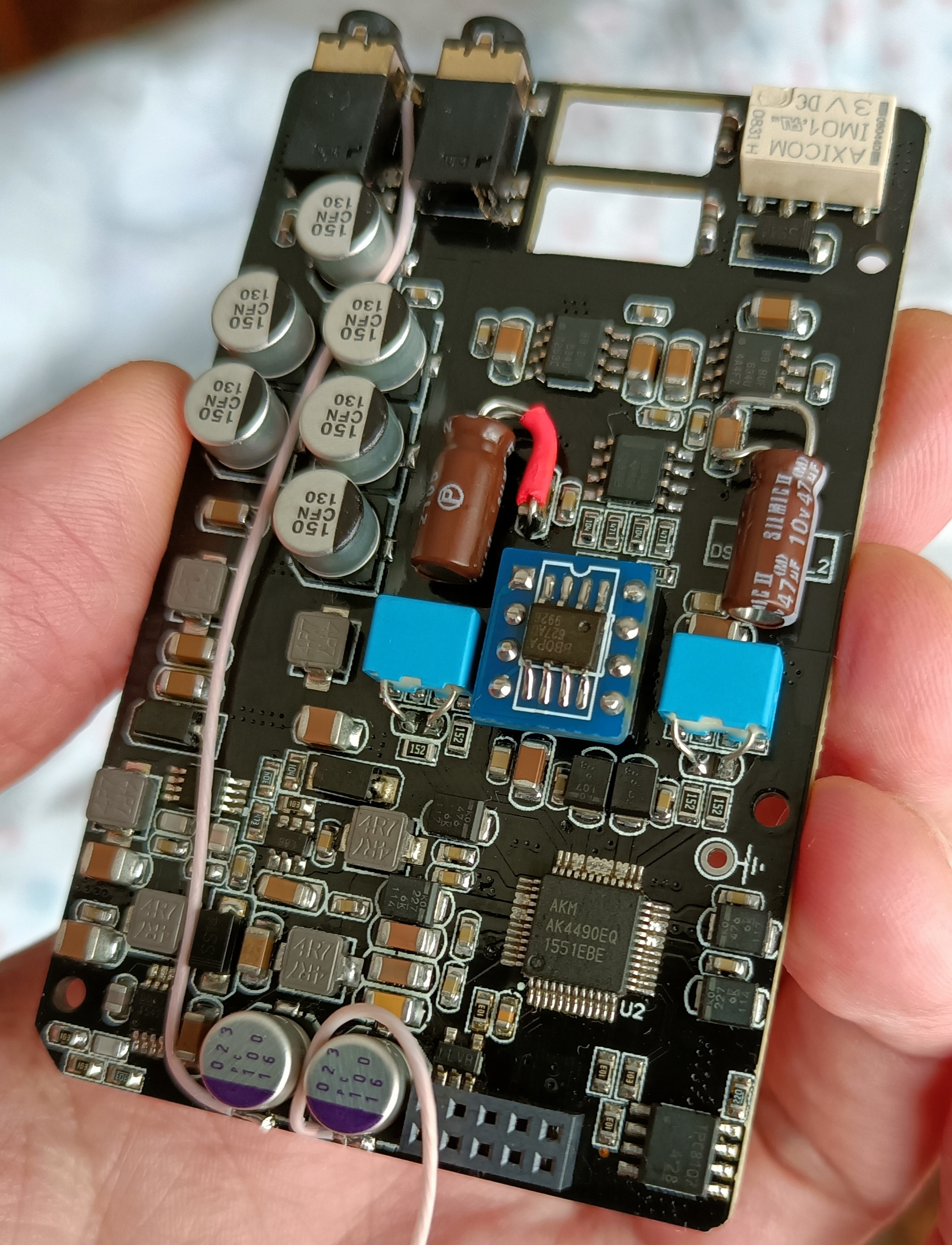
The extension wire socket is way to huge. I need to cut and solder the wires flat on the dip 8 socket, and route the wires outside, to the top or botton cover. And then connect the wires to the top of the extension socket. Then I can connect the opamp outside of the casing. But the problem is there is not enough space between the board. there is only a few mm. space.
I need to cut the extension wires anyway to extend them and bring the extension socket outside of the top or bottom of the casing
I think about three solutions:
1. Cut out the back of the casing, and then there is more space between the boards. I can hold the battery in place with tape, and put the opamp on top of the battery. Pretty rough job.
2. Demolish and take out the 8 pins of the spare dip 8 socket, and solder 8 wires on the 8 pins, and put the pins in the DSD socket. I need to grind the pins to make them shorter. I don't know it this will hold for a longer period, and I don't know if the opamp will blow up if one or more pins stop making contact. I can put some tape on the pins to cover and protect them and hold them in place.
3. Solder 8 wires on the back of the board (other side of the DSD dip 8 socket). And connect the wires to the extension socket. But then the battery doesn't fit in the casing anymore, I need to put the battery outside of the casing.
What is your advice? The V6 sounds pretty good so I think it's worth the effort.


")


