spritzer
Member of the Trade: Mjölnir Audio
- Joined
- Aug 22, 2002
- Posts
- 10,055
- Likes
- 191
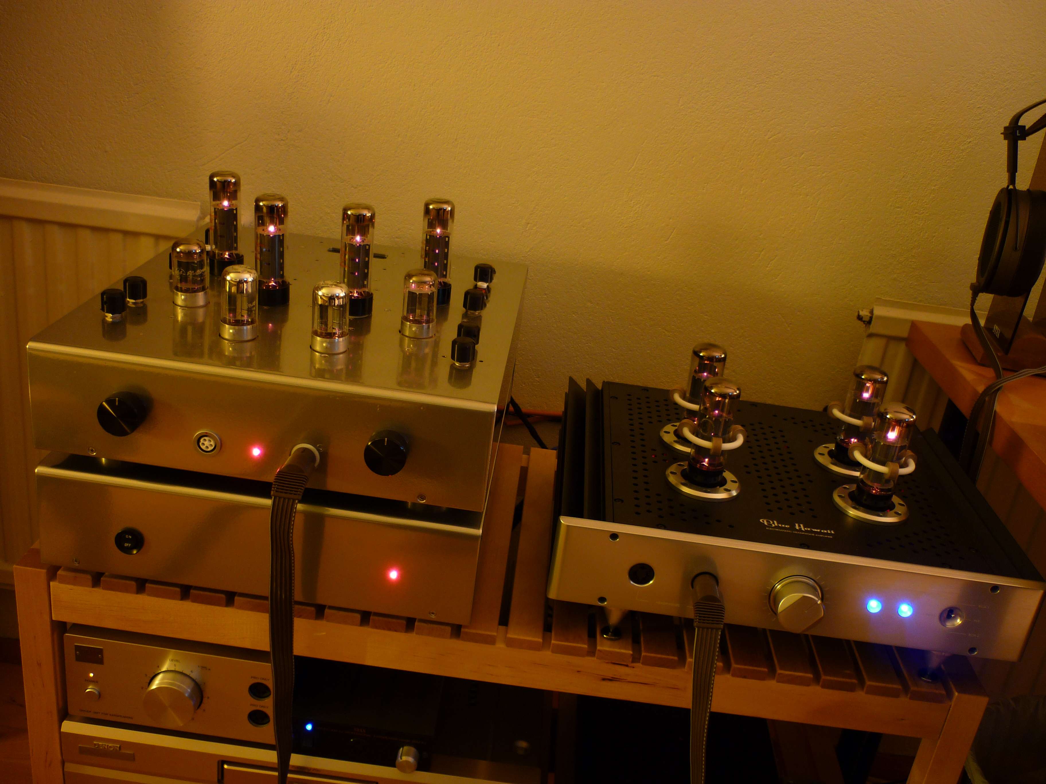
A small update is in order. I've been trying the amp with a quad of 7f7's (the loktal version of the 6SL7) as drivers and it is certainly a different sound, leaner and a bit dryer with less bass bloom. A small issue has crept up though as the amp can't be properly biased with these tubes. It's only off by about 15VDC so it isn't a big deal but should be noted none the less.
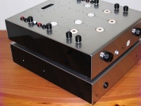
Speaking of biasing the amp, I've been asked on a couple of occasions how this is done now so I figured I'd post it here for posterity. As can be seen on the picture below each channel has 5 test points and 4 pots to adjust the bias.
The amp is mostly DC coupled (as in any change in one stage is carried over to the next stage) but the output stage is AC coupled to the driver stages so effectively isolated.
Looking at the schematic on the first page there are four points marked TP1 and through TP4 and those are indeed the test points. The fifth is ground and connected to the common ground inside the amp. On this amp then black and red are the two test points per stage with white being ground.
For the driver stages we have two pots to adjust, a balance pot that balances the sections (which was there on the original Stax design) and we also have a pot connected to the B+ which acts as a voltage divider to decrease the distortion in the amp. This was a later addition to the design by Dr. Gilmore and really works a treat. Now to bias this stage you place a voltmeter between the two test points and adjust the balance pot for 0VDC. Next step is to adjust the B+ and you do that by placing the red probe on either test point and the other to ground and adjust the second pot for half of the amps B+ voltage. My amp is running at +430VDC so +215VDC would be the target here. One has to go back and check the balance after adjusting to get the correct values so using two voltmeters at the same time would be a good idea.
Now any changes made here will not affect the output stage one bit so it's easy work to roll in some new driver tubes. As I said above, that doesn't mean you can use just about any tube with this amp like Mikhail led his customers to believe. The changes made to the circuit were done for the 6SN7/7N7 in mind so with some tubes you might not be able to bias it properly. There is also the issue of distortion which will increase dramatically with some tubes. For lowest distortion then the 12AT7/ECC81 is the tube of choice but the 6SN7 is a good compromise since it would have been a pain to retrofit noval sockets to this chassis.
Now to adjust the output stage. This is rather simpler with just two test points and two pots which ideally should be adjusted at the same time with two meters running. Both are to be adjusted for 0VDC (something which the stock amp could never do, always stuck at -100VDC) with one probe connected to a test point and the other connected to ground. This adjustment is a bit fiddly as you need to balance the two pots per channel and they work against each other at times but is shouldn't take long to get it down to 0V or there about. Now once the amp has been adjusted it drifts very little, a couple of volts max.
Now one last thing, while I do love the cheap thrill of the loktal tubes I must say I've been having some slight trouble with them. They are known to be a bit noisy due to the pins not having the contact area of their octal cousins and I've been experiencing this from time to time. Could also be due to the quality of these cheap Chinese sockets so I'll probably look into replacing them with some teflon units soon.
Speaking of biasing the amp, I've been asked on a couple of occasions how this is done now so I figured I'd post it here for posterity. As can be seen on the picture below each channel has 5 test points and 4 pots to adjust the bias.

The amp is mostly DC coupled (as in any change in one stage is carried over to the next stage) but the output stage is AC coupled to the driver stages so effectively isolated.
Looking at the schematic on the first page there are four points marked TP1 and through TP4 and those are indeed the test points. The fifth is ground and connected to the common ground inside the amp. On this amp then black and red are the two test points per stage with white being ground.
For the driver stages we have two pots to adjust, a balance pot that balances the sections (which was there on the original Stax design) and we also have a pot connected to the B+ which acts as a voltage divider to decrease the distortion in the amp. This was a later addition to the design by Dr. Gilmore and really works a treat. Now to bias this stage you place a voltmeter between the two test points and adjust the balance pot for 0VDC. Next step is to adjust the B+ and you do that by placing the red probe on either test point and the other to ground and adjust the second pot for half of the amps B+ voltage. My amp is running at +430VDC so +215VDC would be the target here. One has to go back and check the balance after adjusting to get the correct values so using two voltmeters at the same time would be a good idea.
Now any changes made here will not affect the output stage one bit so it's easy work to roll in some new driver tubes. As I said above, that doesn't mean you can use just about any tube with this amp like Mikhail led his customers to believe. The changes made to the circuit were done for the 6SN7/7N7 in mind so with some tubes you might not be able to bias it properly. There is also the issue of distortion which will increase dramatically with some tubes. For lowest distortion then the 12AT7/ECC81 is the tube of choice but the 6SN7 is a good compromise since it would have been a pain to retrofit noval sockets to this chassis.
Now to adjust the output stage. This is rather simpler with just two test points and two pots which ideally should be adjusted at the same time with two meters running. Both are to be adjusted for 0VDC (something which the stock amp could never do, always stuck at -100VDC) with one probe connected to a test point and the other connected to ground. This adjustment is a bit fiddly as you need to balance the two pots per channel and they work against each other at times but is shouldn't take long to get it down to 0V or there about. Now once the amp has been adjusted it drifts very little, a couple of volts max.
Now one last thing, while I do love the cheap thrill of the loktal tubes I must say I've been having some slight trouble with them. They are known to be a bit noisy due to the pins not having the contact area of their octal cousins and I've been experiencing this from time to time. Could also be due to the quality of these cheap Chinese sockets so I'll probably look into replacing them with some teflon units soon.