
spritzer
Member of the Trade: Mjölnir Audio
- Joined
- Aug 22, 2002
- Posts
- 10,055
- Likes
- 191
Warning: High Voltage!! This, along with all other electrostatic amps, use high voltage which is very dangerous and potentially fatal. In this particular amp there are voltages close to 500v with more then enough current to do permanent damage so a novice should never try to work on it. Even when left off for a while the capacitors can still hold a lot of energy so they should be checked before working on the amp/psu.
[size=medium]1: Introduction[/size]
In this thread I, with the help of other qualified members of the community, will address the numerous issues which are common to all the Single Power ES-1/2 amps. With Mikhail being evasive as ever and not repairing the mess he made for him self, it is up to the owners to look elsewhere for service and this thread is intended to guide any techs which will be working on the amps, by listing known issues and ways to fix them.
The main focus of this thread will be on my particular ES-1 which was generously donated to me by our very own Afrikane. I'd like to thank Kane for this kind gesture one more time and giving me a project that will eat up all my spare time for the conceivable future.
 More on that later though. This amp (which had a list price of just under 10k$ as can be seen in the spec sheet) had never functioned as it should, even after being sent in for servicing so Kane got fed up, sold off his electrostatic headphones and put the amp in storage. Earlier this month he put up a post in the Stax thread here where he expressed his wish to give the amp away to whom ever could have use for it. I volunteered to rip it apart for everybody to see and a few weeks later I had it here. This is how it looked when it arrived:
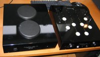
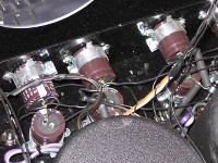
After unpacking this heavy beast (20kg+) I was struck with just how poor quality the chassis is (two metal plates which are cut and bent and help together with 4 screws) and the painted finish is very cheap. Now the amp isn't new so a few scratches are normal but the amp also had a rather large one on top of the amp which had been touched up, badly. Most of the screws also show varying degrees of rust. Enough about that, time to open up the amp chassis:
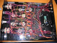


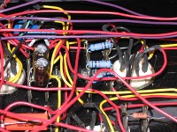
Now if you haven't downloaded and read the spec sheet linked to above I would go and do so. All the items highlighted in yellow are supposed to be included in this amp. Amongst them is a 549$ surcharge for V-caps which you should be able to see in the pictures. I sure couldn't find any and instead I found some generic orange drop coupling caps which on top of that only rated at 400V. The minimum for this amp is 600v... There is also supposed to be about 429$ worth of silver wire inside the amp but all I can find is cheap, solid core PVC coated silver plated wire. What is also missing are the Cardas GRFA RCA sockets which cost 45$. This would have been easy to check but nobody apparently did...
It's not all bad news since the 395$ 4 channel gold stepped attenuators are there but they are just bog standard Goldpoint Mini-V units. The Black Gate cathode resistors are also there but paying 185$ for them is a bit excessive given how much these 100uf/25v F units cost back in 2006 when this amp was made. The digital tube biasing system is there too but I will post a seperate article on that later on.
The over all build quality of the amp section is rather poor IMO. It is filled with the cheapest standoffs known to man and they are even used as part of the signal wiring. All resistors are standard stuff and the tube sockets are absolutely horrid. The soldering is very poor in places and no thought has been given to proper layout with all types of wiring mixed together. Running signal, filament and HV lines together is never a good idea.
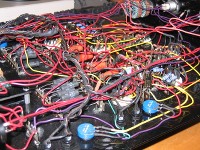
Next step was to open up the PSU and this is what greeted me:
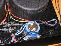

Now open up that spec sheet and see what we have here. Here we are supposed to see 375$ worth of Black Gate caps plus some 589$ worth of V-caps. None to be found and only some basic quality Nichicon 400v caps.
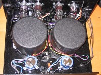
Some of the items paid for were there though such as those heavy Plitron transformers (4.5kg's each) and there were quad regulators used, two for the HV supply and two for the DC filament supply. Those were all bolted to the chassis but as I later found out, there wasn't any thermal compound bonding the two together.
The transformers are a stock Plitron unit (see a picture of the label here) and they are designed so that the cables exit from the bottom of the solid metal chassis. They therefore sit on aluminum brackets supported by a few 10mm standoffs. This has proven to be inadequte as the washer securing the transformer to the bracket is badly bent on both of them and so is the bracket. I sadly forgot to take a picture of the bracket while I was in there though.
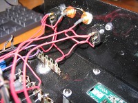
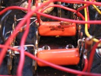
As can be see from the pics then the build quality here is utterly terrible. Just about everything is wired with the same PVC coated black wire which makes troubleshooting that much harder. This chassis design is also a horrible choice here since the whole PSU is built into the bottom with all the connectors, LED's and switches on the top part. There was quite a bit of slack in the wires (which were never fixed in place in any way to the chassis) but this is a bad way to do things.
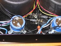
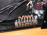
In the last pic you can see the "bias supply" for the headphones which is just a string of 1M resistors, one each for the HE90 and Stax PRO outputs. This is nothing but fail but there is a reason why Mikhail did this which shows that he knew the amp had major design issues.
In the next post I will talk about the known issues with the ES-1/2 amps and what can be done to fix them. In the third post I will document the ongoing journey of my amp where I transform it into what it should have been in the first place.
Stay tuned...
[size=medium]1: Introduction[/size]
In this thread I, with the help of other qualified members of the community, will address the numerous issues which are common to all the Single Power ES-1/2 amps. With Mikhail being evasive as ever and not repairing the mess he made for him self, it is up to the owners to look elsewhere for service and this thread is intended to guide any techs which will be working on the amps, by listing known issues and ways to fix them.
The main focus of this thread will be on my particular ES-1 which was generously donated to me by our very own Afrikane. I'd like to thank Kane for this kind gesture one more time and giving me a project that will eat up all my spare time for the conceivable future.

After unpacking this heavy beast (20kg+) I was struck with just how poor quality the chassis is (two metal plates which are cut and bent and help together with 4 screws) and the painted finish is very cheap. Now the amp isn't new so a few scratches are normal but the amp also had a rather large one on top of the amp which had been touched up, badly. Most of the screws also show varying degrees of rust. Enough about that, time to open up the amp chassis:


Now if you haven't downloaded and read the spec sheet linked to above I would go and do so. All the items highlighted in yellow are supposed to be included in this amp. Amongst them is a 549$ surcharge for V-caps which you should be able to see in the pictures. I sure couldn't find any and instead I found some generic orange drop coupling caps which on top of that only rated at 400V. The minimum for this amp is 600v... There is also supposed to be about 429$ worth of silver wire inside the amp but all I can find is cheap, solid core PVC coated silver plated wire. What is also missing are the Cardas GRFA RCA sockets which cost 45$. This would have been easy to check but nobody apparently did...
It's not all bad news since the 395$ 4 channel gold stepped attenuators are there but they are just bog standard Goldpoint Mini-V units. The Black Gate cathode resistors are also there but paying 185$ for them is a bit excessive given how much these 100uf/25v F units cost back in 2006 when this amp was made. The digital tube biasing system is there too but I will post a seperate article on that later on.
The over all build quality of the amp section is rather poor IMO. It is filled with the cheapest standoffs known to man and they are even used as part of the signal wiring. All resistors are standard stuff and the tube sockets are absolutely horrid. The soldering is very poor in places and no thought has been given to proper layout with all types of wiring mixed together. Running signal, filament and HV lines together is never a good idea.
Next step was to open up the PSU and this is what greeted me:


Now open up that spec sheet and see what we have here. Here we are supposed to see 375$ worth of Black Gate caps plus some 589$ worth of V-caps. None to be found and only some basic quality Nichicon 400v caps.
Some of the items paid for were there though such as those heavy Plitron transformers (4.5kg's each) and there were quad regulators used, two for the HV supply and two for the DC filament supply. Those were all bolted to the chassis but as I later found out, there wasn't any thermal compound bonding the two together.
The transformers are a stock Plitron unit (see a picture of the label here) and they are designed so that the cables exit from the bottom of the solid metal chassis. They therefore sit on aluminum brackets supported by a few 10mm standoffs. This has proven to be inadequte as the washer securing the transformer to the bracket is badly bent on both of them and so is the bracket. I sadly forgot to take a picture of the bracket while I was in there though.
As can be see from the pics then the build quality here is utterly terrible. Just about everything is wired with the same PVC coated black wire which makes troubleshooting that much harder. This chassis design is also a horrible choice here since the whole PSU is built into the bottom with all the connectors, LED's and switches on the top part. There was quite a bit of slack in the wires (which were never fixed in place in any way to the chassis) but this is a bad way to do things.
In the last pic you can see the "bias supply" for the headphones which is just a string of 1M resistors, one each for the HE90 and Stax PRO outputs. This is nothing but fail but there is a reason why Mikhail did this which shows that he knew the amp had major design issues.
In the next post I will talk about the known issues with the ES-1/2 amps and what can be done to fix them. In the third post I will document the ongoing journey of my amp where I transform it into what it should have been in the first place.
Stay tuned...


