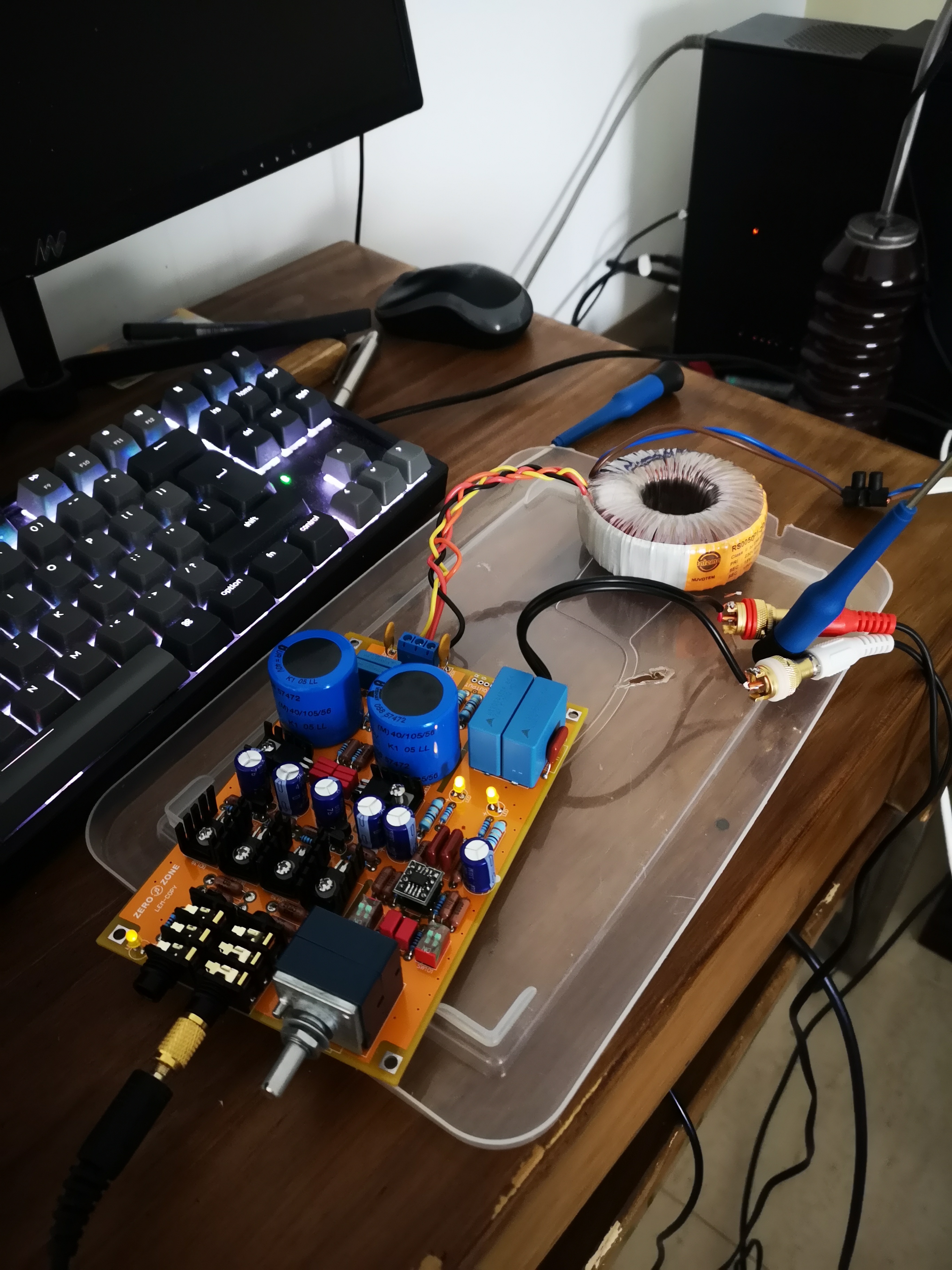
The "Lovely Cube" Headphone Amp (Lehmann Black Cube Linear Clone)
Dec 17, 2011 at 8:13 AM Post #931 of 1,624
How can I reduce DC offset, I measured 17mV on the right channel, and 6mV on the left, witch resistors should I swap ?(It's worth noting, that I don't have the lovely cube, what i actually have, is an eBay clone of the BCL, but it's essentially the same thing IMO )
 
Dec 17, 2011 at 10:24 AM Post #932 of 1,624
Hi there,
 
just today arrived my LC, and I have some questions:
 
1. The voltage regulators are National. Are they of good quality or I need to change them? I was thinking to use On-semi, will they be ok?
2. Near them I found a strange component, I'm not sure, but it could be a trimmer ( see photo below). Is it for DC offset regulation?
3. BD 139 and 140 are ST. I need to change them?
4. Can you tell me the caps that I need to replace please?


Thank you in advance


Dec 17, 2011 at 12:47 PM Post #934 of 1,624


Quote:
How can I reduce DC offset, I measured 17mV on the right channel, and 6mV on the left, witch resistors should I swap ?(It's worth noting, that I don't have the lovely cube, what i actually have, is an eBay clone of the BCL, but it's essentially the same thing IMO )

 
You can find matched BC550/560 transistors but it is not worth because soldering and de-soldering them is tricky process. The best way to low down DC offset in your amplifier is to replace 1k1 resistors with trimmer pot and 1K resistor in serial connection (that will make usable range from 1K to 1K2 which is enough for voltage tuning between 14V to 16V. Also you can put there one 2K trimmer pot but that I would not recommend because voltage tuning will be less precise AND trimmer pot has deviation (usually 2%) that can make your voltages different - every time when you turn on your amplifier. You can use vertical or horizontal trimmer pot. 100R resistor leave as it is.
 
From my experience with LC topology I know that below 14V regulated DC voltage after regulators, DC offset on headphone out is negligible and you do not need matched transistors (BC and BD) and deviation in manufacturing process is enough tight. But when you try to use +/-18V DC and more, then matched transistors are of big importance. Unfortunately "matching transistors right on the table" is only the first part of story because when you match something that means that you need exactly the same environment for what you have matched. That means that matched transistors must always have the same temperature (transistor characteristic varies with temperature). So, it is not easy to do without custom made PCB and heat sinks. In old amplifiers that was done with 3 pin sockets that were soldered on the PCB and in there different transistors were placed and tried. When the lowest DC (or the best characteristic on the scope) was achieved transistors were soldered.


Quote:
Hi there,
 
just today arrived my LC, and I have some questions:
 
1. The voltage regulators are National. Are they of good quality or I need to change them? I was thinking to use On-semi, will they be ok?
2. Near them I found a strange component, I'm not sure, but it could be a trimmer ( see photo below). Is it for DC offset regulation?
3. BD 139 and 140 are ST. I need to change them?
4. Can you tell me the caps that I need to replace please?


Thank you in advance


1. Every voltage regulator that is genuine is good enough. Fakes are not good.
 
2. This trimmer is for tuning DC voltage, From the picture I see that genuine topology has drawback, because there is no enough room for two trimmer pots. There only one voltage can be tuned. But that does not matter a lot and if your offset on headphone out is to high, then you can change voltage with this trimmer - and lower DC offset.
 
3. BD made by ST is good as all others. Since Philips is gone there is no difference between all BD139/140 transistors. Person that worked in Phillips told me that Phillips was manufacturing transistors with tolerance under 1%. Today, all factories make BDs within 5% (5 times worse)...
 
4.Caps that you could replace (try different) are those around opamp (MKT and Tin Foil) and electrolytic capacitors (470 uF) near BC/BD transistors and opamp. If you want to change capacitors near BD transistors do not go to high with capacitance and do not buy ultra low ESR capacitors because your regulators might start to ring (oscillate) in high frequency region. Furthermore I would personally (but that's me :) ) change Cady capacitors (TWO green Vishay MKT 1822 - 0.15uF, the rest FOUR are in Vin and Vout circuit) with tantalum 10uF (watch out polarity) because this position is where tantalums are the best and this will give you more headroom for low ESR caps near BD regulators (less ringing - according to data sheet) and it will suppress voltage noises (according to data sheet).
 
 
Dec 17, 2011 at 12:49 PM Post #935 of 1,624
This is the board.


please don't hesitate to put signs in the parts that you suggest, I can change.
Overall the caps, beacuse for the others components I understand.
My doubts are  on the quality of ST and National ( now installed in my LC ) vs. Fairchild and On Semi.
Will be an important upgrade?
 
Dec 17, 2011 at 1:51 PM Post #936 of 1,624


Quote:
This is the board.


please don't hesitate to put signs in the parts that you suggest, I can change.
Overall the caps, beacuse for the others components I understand.
My doubts are  on the quality of ST and National ( now installed in my LC ) vs. Fairchild and On Semi.
Will be an important upgrade?

 
The most important parts are transistors and capacitors. If you do not have matched transistors, changing those with another (unmatched) is not worth. Big influence in sound picture have high pass (DC blocking - in this case) and low pass capacitors. Second are opamp coupling capacitors and third are supply capacitors near transistors.
 
1. Low pass filter (blue capacitors from the left side of OPAMP / close to ALPS pot) should be MKP/FKP or polystyrene. MKT/MKS does job but not enough. MKT/MKS is good for power supply -  not in the signal path.
 
2. Try to replace coupling (yellow capacitors) near OPAMP with Polystyrene (Styroflex) 20nF or 10nF. Here is excellent place for them.
 
3. Signal caps on input (DC blocking) have good voltage but bigger capacitance would be better (3,3 uF is good, more is better). If you are able, try to find MKT (10uF) and couple them with MKP. Or you can make good combination with big MKC 63V (4,7 uF) and fast MKP 250V (33 nF) in a parallel connection.
 
4. Blue elcos near transistors are Philips BC?I changed them with Panasonic FC (NOT FM) and there is more depth and bass. But BC seems to have faster response (more bright). Cerafine and Silmic are too big and demand lower temperature environment (85C). You should go with capacitors that are ranked within 105C.
 
5. Blue elcos near opamp. They are energy tanks and with resistor (47R)  they make RC filter. You can change them as elcos near BD transistors. I put here Panasonic FC. Others put here Cerafine, Silmic, etc... Be aware that Cerafine won't fit if it is bigger than 470 uF / 25V, and Silmic won't fit (at all) if it is bigger than 220 uF / 25V. Quality matters a lot (dielectric isolation or rated voltage). If it is rated as 50V it will have better characteristic than something rated as 25V. But, there is not enough place for 50V...
 
6. This is trimmer pot. With it you can tune ONLY POSITIVE VOLTAGE (LM 317) and lower your DC offset.


All this depends on other parts in your amplifier. The best would be if you change one part (for example input DC caps and opamp coupling) and listen to music. If your demands are satisfied - your tuning stops there. If you are not satisfied you might continue with upgrades. You can't be sure that other people choices will be the best bet because we all have different DAC, headphones, type of music, media (CD/MP3/DAT/WAV), different music tastes, etc, etc...
 
 
Dec 17, 2011 at 7:51 PM Post #938 of 1,624


Quote:
Can you point out the resistors that you were talking about, because the closest I have is 1.5k resistors (actually 4 of them, so I think that you were talking about them) 
https://picasaweb.google.com/114049227892902856235/LehmannBCLCloneBuild?authkey=Gv1sRgCNij44XJxeb2eA - here a some pics of my build BTW.
 
Thanks.


These two. Resistors before opamp.  With 470uF capacitors they make RC filter that isolates opamp circuit. RC is used for noise and ripple suppression.
 
 
Dec 18, 2011 at 1:23 PM Post #940 of 1,624


Quote:
 
What is the right value of them ?


 Right value depends on frequency range that you want in your opamp. Stock capacitor is 100pF. Input impedance is variable and starts from 10k (when your volume pot is to max) and ends with 60k (when your pot is to min).
 
With 100pF you will have:
 
volume to max - 10k, 100pF - low pass filter = 160kHz
volume to min - 60k, 100pF - low pass filter = 26 kHz


Dec 19, 2011 at 1:17 AM Post #941 of 1,624
man i want to order a LC Premium to try but apparently Stephen doesnt sell it locally (Hong Kong)
 
Dec 21, 2011 at 3:43 PM Post #943 of 1,624


Quote:
Looks like it has BlaBlaBla's pot mod in there. Can you take a picture of your entire board?


Hi Francis,
what did you say was correct.
I attach the Stephen's answer :
 
"If I remember right , your board has a trimmer , which is used in order to make negative rail at the nearest voltage with positive rail.  LM317 output 15.01V and LM337 output 15.01V , and the DC offsets are very low indeed. You can measure them if you have a multimeter and if you know how to measure.  Taking extremely caution when measuring in order not to get electric shock and any shortage of circuit."


Dec 21, 2011 at 4:44 PM Post #944 of 1,624


Quote:
Hi Francis,
what did you say was correct.
I attach the Stephen's answer :
 
"If I remember right , your board has a trimmer , which is used in order to make negative rail at the nearest voltage with positive rail.  LM317 output 15.01V and LM337 output 15.01V , and the DC offsets are very low indeed. You can measure them if you have a multimeter and if you know how to measure.  Taking extremely caution when measuring in order not to get electric shock and any shortage of circuit."


I wouldn't bother myself with voltage right out of regulators. I would give more attention to DC offset. Point is not in achieving equally voltages between negative and positive rail. Transistors have their own characteristic so if you want to pull out best from your setup then you must try to find voltages that will give you 0V (or close) DC offset on headphone out. When DC offset is close to 0V that means that headphone coils are right in the middle position and that means that their reaction will be exactly the same for negative and for positive voltage swing. This is very important for high frequency signal and for low impedance headphones. Even a low voltage can pull out coil on one side of driver and some dynamic is lost. Well, this is simplified description and the closest term that describes this behavior is: "some amount of DC offset will slow down headphone dynamics", more than that will fry their coils. Lets say that for Grado 50-80 mV AC is good enough for normal listening. And what happens if there is 15mV of constant DC offset? That is 1/5 of output signal. For high impedance headphones 15 mV is not so extreme because they need 200-300 mV AC for good listening. That is 1/15 of output signal.


Users who are viewing this thread

Back
Top