The "Lovely Cube" Headphone Amp (Lehmann Black Cube Linear Clone)
Nov 10, 2011 at 5:51 PM Post #856 of 1,624


Quote:
Looking at assembling a Lovely cube to mod and play around with, but I was wondering: If I wanted to be able to use it as a pre-amp, would I just reroute the leads to one of the headphone jacks to RCA's on the back panel (twisted and shielded, maybe coaxial pairs)? If so, which jack should I use for the preamp? (I read that one is line out-muted and the other is line-out?).  Also, would it be adventagous to create a simple grounded-shield to cover the transformer?


Since your using it as a pre-amp I don't think it will matter.
I would use the jack furthest away from the volume knob if you want to keep the mute function of the LC pre amp out. Basic behavior is if you plug your phones into the jack furthest way from the volume it will mute the LC's pre-amp out.
 
Check out this photo of the underside of the board.


You can see the Alps pot mounting little holes on the lower left hand side, then 2 pairs of 8 large holes for the 2 - 1/4'' jacks. the traces on the far right lead up to the pre-amp out.
 
Populated top view of the board for reference:


Hope this helps.
 
Nov 10, 2011 at 6:08 PM Post #857 of 1,624
He tried a lot of things. I was also thinking about wrong connections but what I have seen from pictures everything seems OK. Only part that can be wrong is (maybe) volume potentiometer. Because it is logarithmic.

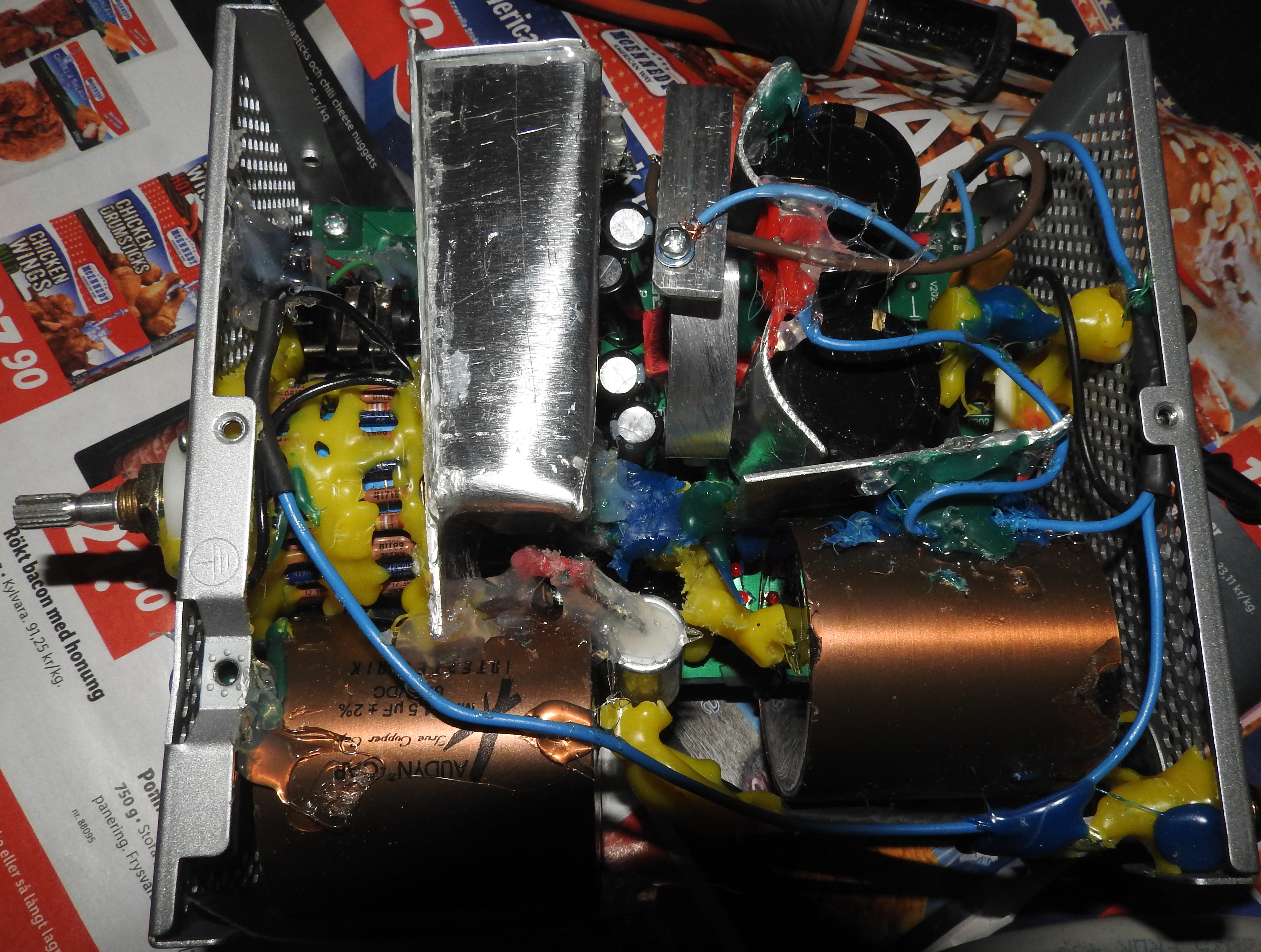
For comparison I soldered my own Lovely Cube. I did  few minor changes in the power supply and near BD transistors. I made three channel supply (separated channels) for output and opamp. I wanted to know what will happen. I put 1200uFon each output. Elna Silmic II in opamp power supply. Some old ERO 1841 (bypassed with russian polystyrene capacitors) on input. Polystyrene for opamp coupling. Etc, etc... A lot of capacitors in power supply.
 
Maybe it is silly but it sounds good. On Grado SR225 this funny hand made amp kicks ass. Bass is deep. Very very deep. Highs are mellow but enough fast. Mids are in front. Sound stage is wider and deeper than on Lovely Cube. If I compare the same OPA2604 in Lovely Cube, difference is like heaven and earth. Lovely Cube is maybe faster but also more sterile. This is more old fashion with grunt and deep power. I must admit that I do not like when people listen to oscilloscope and talking about how good is 96 Khz signal in their amplifier. I give a **** about measuring and about 96 kHz when I am able to hear only 18kHz. My ears are the best oscilloscope and they have final word.
 
Also what I noticed is that this amp does not get warm with stock 1.2K resistors. After turning off there is no DC over voltage on output, and without opamp, DC offset is 0. In Lovely Cube, without opamp, DC offset was 6 volts (SIX VOLTS). So you can imagine what will happen in Lovely Cube if your opamp suddenly stops to work... Here this is not the case. Also this amp has more power because it doesn't sag on very demanding parts in classical music. Bass is always here, mids are always here and highs are always here, no matter what. Drives like a tank.
 
There is no noise, what is really interesting, because of lots of wires and connections. I tried to implement multiple layer grounding (separate grounds for signal, opamp and supply but that did not work. Too much noise. When I had done star ground (below PCB, close to capacitors and rectifiers) noise was gone completely. 5W resistors are on borad because I didn't want to pull them out, but they are not in function.


It is not on the picture but I put a mute switch in front, that allows me to disconnect headphones without making a short circuit on BD-s. Also, for safety measures I always leave amplifier for 3-5 minutes to work without headphones (mute on)... This is still hand made amplifier. Who knows what might happen. %) If nothing goes on fire I start to listen to music. :) I put another transformer for driving OPA2604 (10VA). It is not on the picture. It is added later.
 
Now I have plans to make another amplifier but with more changes and with less wasted space. I think that after this I would never buy an amp from manufacturer or seller. Because of three reasons: First I like to DIY, second I do not have money for buying something that is made for 300 USD and costs 1300 USD, and finally the third reason - I listen to MP3 mostly and benefit from 4000 USD amplifier, is completely gone right from start.
 
And fourth reason - I am sick when I see overheated amplifiers with tiny transformers.. Put that amplifier in big box, give it big transformer, and see how it sings...
 
Quote:
How are things, miky?
 
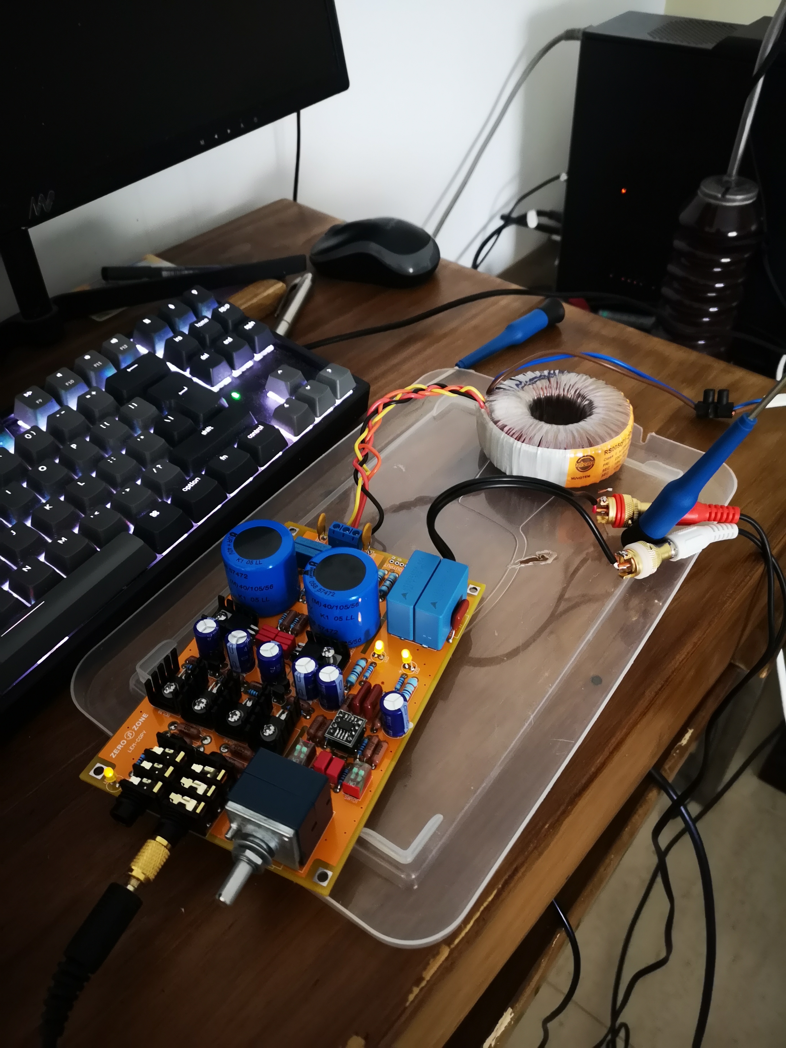
 If the good advices from francisdemarte has not brought a solution, I think it might be an idea to check if the signal is present at the output of the opamp. You could use at 1k sinus wave at the input (and turn up the volume a bit). A multimeter should show the AC signal at the points shown in the picture (which are directly connected to the output pins of the opamp). You should easily be able to get lots of Volt out of the chip.
 
For that matter you send music into it and take the signal from here,  and (together with a ground lead) connect to a pre-amp input).
Preferably connect through a 100-1000 Ohm resistor close to the output, in this case).
 
I strongly suspect that something is wrong with the op amp or its connections.
 
A pair of completely wrong resistor values is theoretically also a possibility, in a case like this.


Good luck. Olaf


Nov 10, 2011 at 7:50 PM Post #858 of 1,624
Another comment to the miky2011 case:
To ensure good grounding the ring with solder tag ’A’ should be on the other side (inside) of the white plastic isolator. It seem to me from the photo that the only grounding you will get here (esp with a coated surface of the cabinet wall) would be a rather insecure contact of the ring with the outer surface of the screw part of the RCA connector. Olaf


Nov 10, 2011 at 9:44 PM Post #859 of 1,624
Hopefully Milky finds the issue with his amp and gets it up and running.
 
Hey BlaBlaBla, you should start selling your own Ultra-Lovely-Cube with all your modifications!  
 
Nov 10, 2011 at 10:45 PM Post #860 of 1,624

Doh! didn't even see that it had a dedicated preamp-output pad. This is post-fader right? so the potentiometer can adjust the output?
Quote:
Since your using it as a pre-amp I don't think it will matter.
I would use the jack furthest away from the volume knob if you want to keep the mute function of the LC pre amp out. Basic behavior is if you plug your phones into the jack furthest way from the volume it will mute the LC's pre-amp out.


Nov 11, 2011 at 3:09 PM Post #862 of 1,624
Hello,
 
     I checked all the components in place and value. I think that all is right in this sense.
 
     The only thing that I dont have tested is Pot ALPS.  What is the easiest way to check it? It´s necessary remove from PCB?
 
     I want to thank to everyone the valuable assistance you are given me. Specially to Blablabla. Thanks !!
 
     Its true. The lack of amplification occurs in the two channels equally. The problem can not be so hard.
 
    With 10db, 18db and 20db,  ampliffication occurs but not nearly the amplification that should be right.
 
    Is desperate. I put the photos.
 
    https://www.dropbox.com/gallery/2747771/1/Lovely?h=53f1a2
 
regards.... i hope your opinions.


Nov 11, 2011 at 6:12 PM Post #863 of 1,624


Quote:
Hello,
 
     I checked all the components in place and value. I think that all is right in this sense.
 
     The only thing that I dont have tested is Pot ALPS.  What is the easiest way to check it? It´s necessary remove from PCB?
 
     I want to thank to everyone the valuable assistance you are given me. Specially to Blablabla. Thanks !!
 
     Its true. The lack of amplification occurs in the two channels equally. The problem can not be so hard.
 
    With 10db, 18db and 20db,  ampliffication occurs but not nearly the amplification that should be right.
 
    Is desperate. I put the photos.
 
    https://www.dropbox.com/gallery/2747771/1/Lovely?h=53f1a2
 
regards.... i hope your opinions.


You can measure the Alps, without taking it out, Turn off the power, remove the op amp and also the input cables. Turn the volume knob to its maximum position. The resistance should now measure zero between in and out pins (they are shorted). Turn it all the way down and it will measure 50k (or whatever the nominal value is). Notice that when turning it gradually down from the max volume position, there will be little change of resistance towards the end, because of its logarithmic nature ).
 
Good to see that you have fixed the grounding at the input.
 
The main problem is in the op-amp, I still believe.
 
Olaf


Nov 13, 2011 at 5:32 PM Post #864 of 1,624
   Thanks for your posts.
      
    Chetlanin, you say that the main problem maybe is in the op-amp.
    But ....Where is the problem? All components are in place. I have reflow the solders... resistors and capacitors are in right values.
 
    What I can see in the PCB?
    What I can measure?


Nov 13, 2011 at 7:28 PM Post #865 of 1,624
I'm going to have to agree with chetlanin. I suspect it's either the op-amps or something near that area. Maybe the op-amps are could be damaged?
 
Milky do you have any way of verifying the op-amps you have are working? Maybe you can wire up a quick op-amp tester: http://tangentsoft.net/elec/opamp-tester.html


Nov 14, 2011 at 12:19 PM Post #866 of 1,624
Hi francisdemarte,
 
    I tried with three differents op-amps : stock lovely 2134, stock lovely 2111AM and an original 2134 (wich appears in the photos) with the same result and same poor amplification.


Nov 14, 2011 at 12:20 PM Post #867 of 1,624
Not to derail, but thanks for the idea on the op amp tester! I think I'll build one, it looks pretty useful
 
Quote:
I'm going to have to agree with chetlanin. I suspect it's either the op-amps or something near that area. Maybe the op-amps are could be damaged?
 
Milky do you have any way of verifying the op-amps you have are working? Maybe you can wire up a quick op-amp tester: http://tangentsoft.net/elec/opamp-tester.html


Nov 14, 2011 at 12:59 PM Post #868 of 1,624
That is interesting... I tried lots of opamps and difference is minor. Maybe OPA 2604 and OPA 627 have the biggest amplification (2-5% bigger). This is probably because different sound stage (OPA2604 and OPA 627 have strong mids). All others are the same. I haven't seen any difference. I always buy opamps from two trusted sellers (USA).
 
Sellers:
 
http://www.ebay.com/itm/Burr-Brown-OPA2134-dual-soundplus-audio-op-amp-ic-dip-/260742563447?pt=LH_DefaultDomain_0&hash=item3cb577c677
 
http://www.ebay.com/itm/Burr-Brown-OPA2107-precision-dual-difet-op-amp-ic-dip-/260655044299?pt=LH_DefaultDomain_0&hash=item3cb04056cb
 
http://www.ebay.com/itm/Burr-Brown-OPA2604-fet-input-low-distortion-op-amp-ic-/260742565803?pt=LH_DefaultDomain_0&hash=item3cb577cfab
 
http://www.ebay.com/itm/OPA2111-KP-dual-Low-Noise-DiFET-OpAmp-Pro-audio-1-/180658456056?pt=LH_DefaultDomain_0&hash=item2a101545f8
 
http://www.ebay.com/itm/OPA2132-PA-FET-Input-Dual-Op-Amp-High-Speed-OpAmp-x2-/170712816483?pt=LH_DefaultDomain_0&hash=item27bf46db63
 
Something is wrong with PCB. Or opamps are fake... :) I do not want to be rude and do not want to offense anyone, but I am always trying not to buy from sellers who are not in Japan, USA, Canada, New Zeland, Europe. I bought two pairs of headphones. One directly from Japan and one from seller in China. Headphones "almost" look the same (difference in language) but they don't sound the same. Lets say that headphones from Japan are miles ahead.


Quote:
Hi francisdemarte,
 
    I tried with three differents op-amps : stock lovely 2134, stock lovely 2111AM and an original 2134 (wich appears in the photos) with the same result and same poor amplification.


Nov 14, 2011 at 2:30 PM Post #869 of 1,624
One more idea. Have you tested those DIP switches to make sure they are working? I read they can be easily damaged if you overheat them soldering them on. Put your meter on continuity test mode and make sure they go ON and OFF as intended.
 
At this point you may want to consider sending the board off to someone close to debug for you. Where are  you located Milky?  
 
Nov 16, 2011 at 8:34 AM Post #870 of 1,624
 
 
   Francisdemarte,   DIP are working right. I have tested with multimeter the on/off function.
 
   I'm in Spain. Barcelona.
 
   You think that MKP1837 (22nF) capacitors round the opamp can have any problem? Its the only one that I have not change. 


Users who are viewing this thread

Back
Top