The "Lovely Cube" Headphone Amp (Lehmann Black Cube Linear Clone)
Oct 14, 2011 at 12:37 PM Post #826 of 1,624
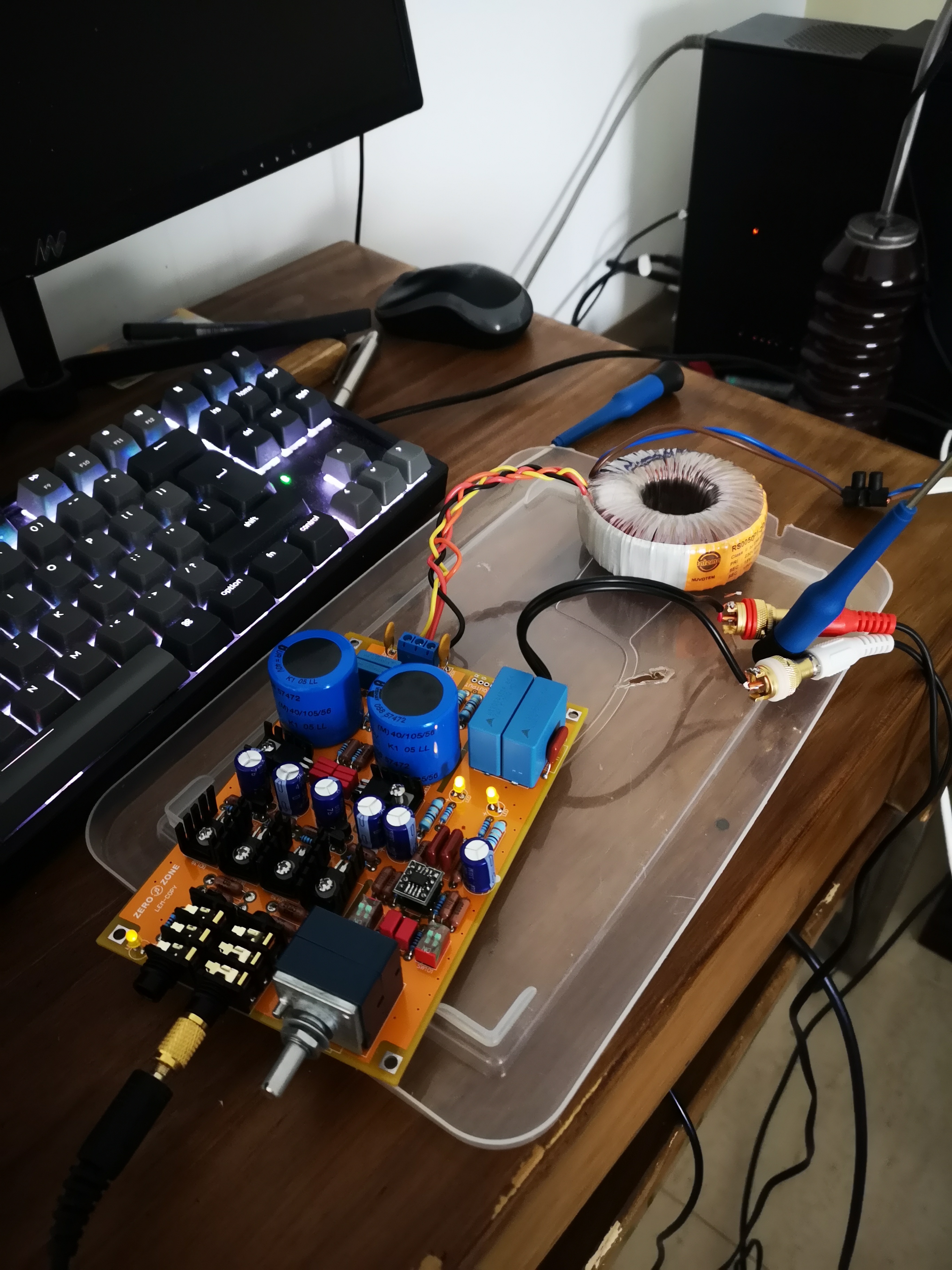
Difficult to go further about the transformer, miky. Personally I do not believe that it is the way to go to improve the amp, as I said.
 
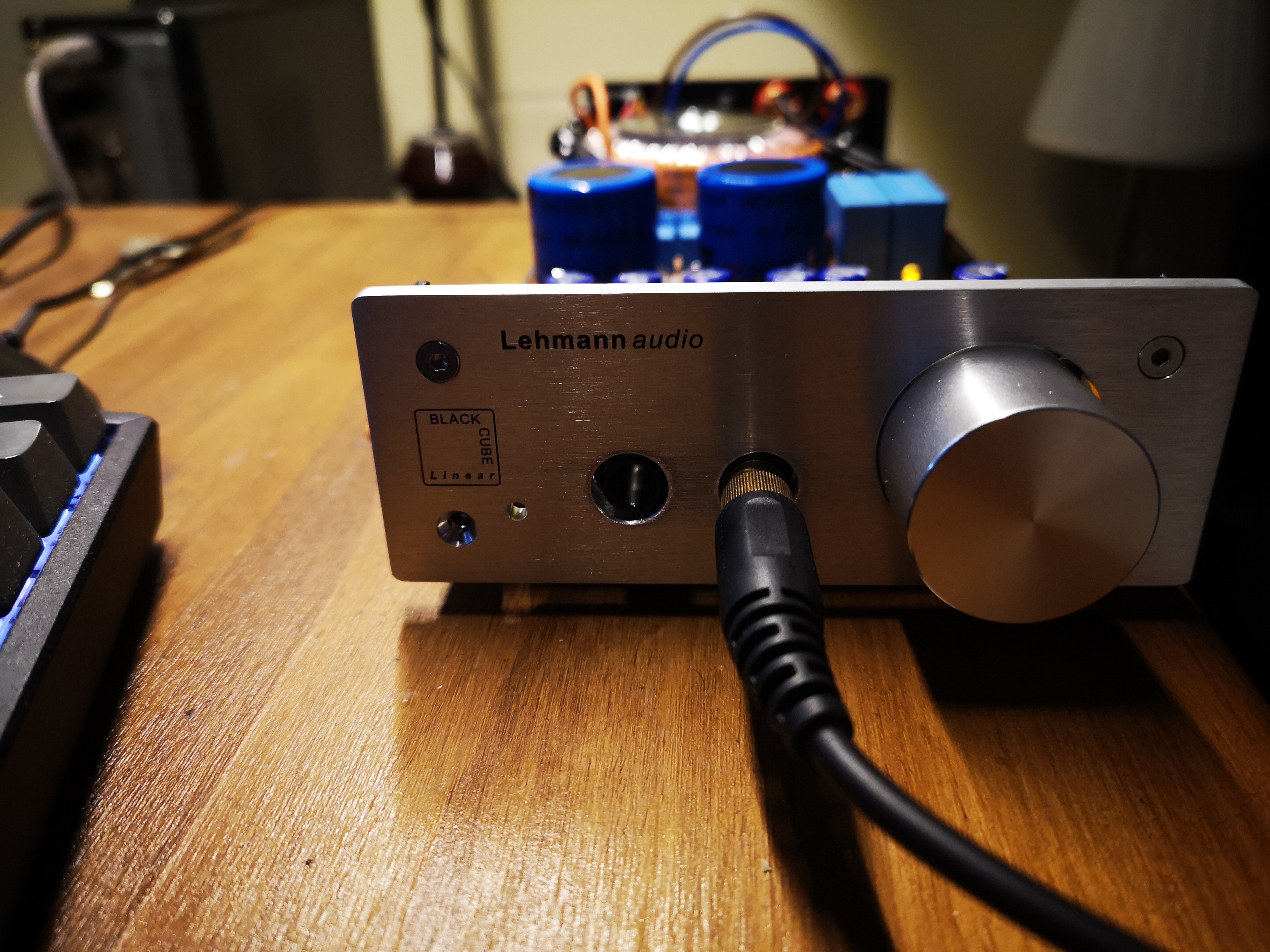
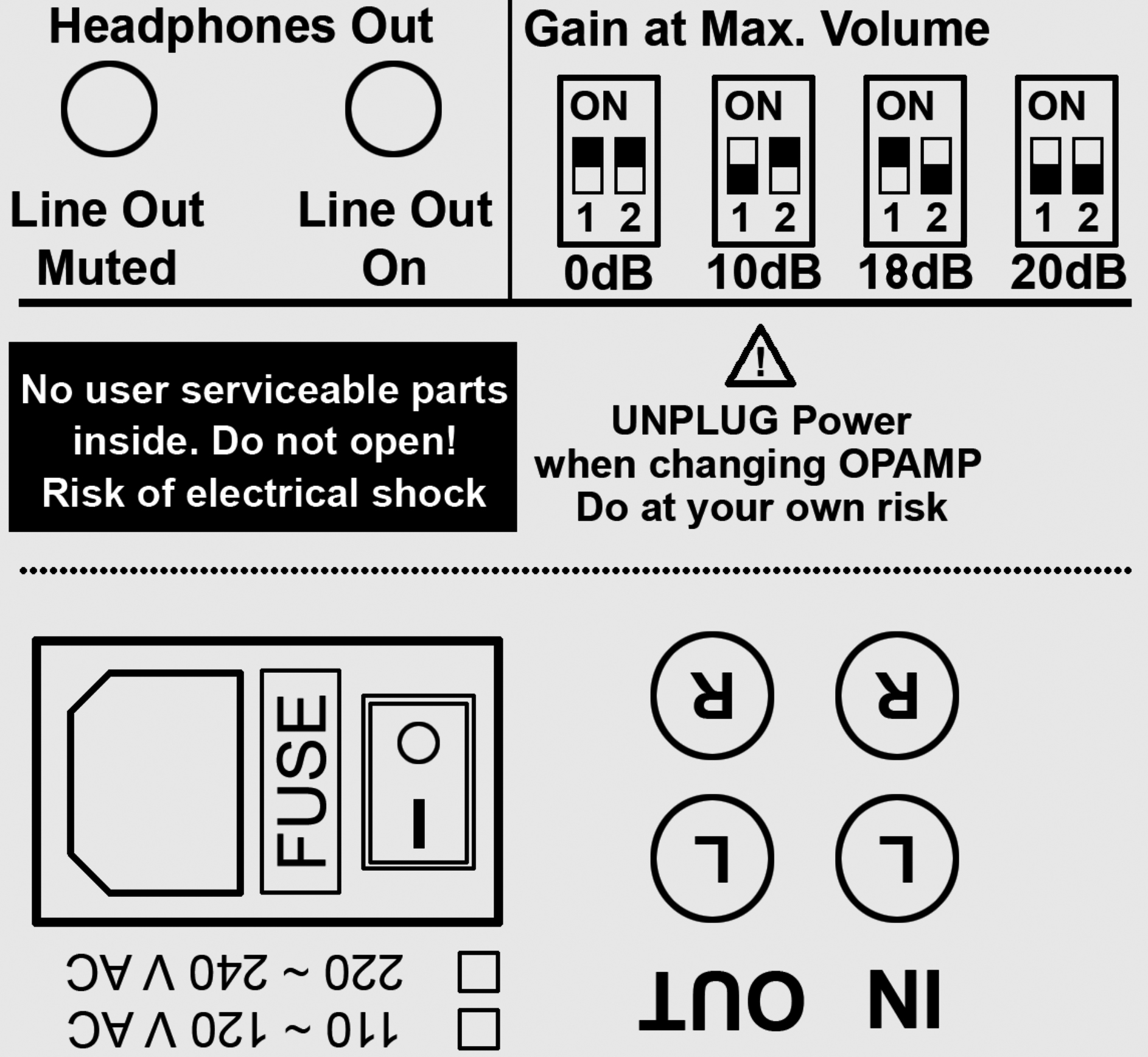
Listen, why copy the Lehmann? Funny idea, but you can make this amp much, much better than the Lehmann by concentrating on a few important things, the weak spots so to speak, rather than changing resistor types and capacitors which are highly unlikely to make any significant difference. First: You can simply put in a better op-amp, and it is highly likely that you already have surpassed the Lehmann, sonically speaking. Second: You must concentrate on the the non-linear components, and that means the transistors. The Chinese stuff (and the recently made Western stuff in general) is not considered the best. Find the best of the older types you can (for example old stock Philips or Siemens made in Europe in the second half of the last century). If necessary pull it from old equipment. Match the transistors in pairs before soldering it into the amp. That is all, in my opinion. No wait, I would add a couple of minor mods which to me has some meaning: Find the right setting of the sensitivity switch and solder the resistor(s) in place. In addition -and here I am w Lehmann - solder the chosen opamp into the board. Really secure connections are of great importance, esp in the long run. Olaf
 
 
Oct 14, 2011 at 7:57 PM Post #827 of 1,624
Improvement you can achieve in two ways. In most cases cooling is of great importance, second is the power supply. On both companies trying to save money. If you want to make something unique, you should try to make LC on your own. Lovely Cube is simple and effective amplifier. Start with power supply. First that might improve things is to separate power supply for transistors and for opamp. Opamp is very sensitive part and demands the best psu that you can built. Also opamp does not like to share power with other fast devices (transistors, oscillators etc...) Second, power stage might be better if channels are separated, which means, capacitors for left and for right channels could be independent, regulators also. There is enormous things that can downgrade or improve results. Zener diode instead R2 resistors? Why not. It work perfectly for LMs. Double bridge rectifier? Why not. They are very cheap. If you don't try you won't know.
 
Right now I am building something like that. My philosophy is not to search for the best amplifier or project arround and work on it next four years- But pull out the best from simple topology (schematic) that I currently own, and that can be easily built.
 
If you are buying new transformer, buy a big one. One day you might fintd it useful in another amplifier/DAC/DIY project. Transformers can last forever if you do not kick them around or smash them with hammer.
 
30VA is not 30W. This depends on your load. It can be 25W but also 15W. If we look for the worst scenario then 15W is 7W/channel or 0.5A/channel... Bigger transformer will have more energy in reserve. Especially during cold start, or when driving your equipment on limit. It is not the same if your transformer has lower value arround 15W (30VA) or arround 30W (60VA).
 
Lots of people say that if you need 10VA  for B class amplifier, for pure A class you need 3x more. (A/B class is arround 2x). The same goes for cooling and heatsinks. :)
 
 
Quote:
 
 
Great thread !!! Thanks for your answers ...
 
  I bought the "LovelyCube" for the fun of being able a "exact" copy of Lehmann BCL. That's my goal. 
normal_smile .gif

 
  That is the reason why I like to know what type of components is mounted in the Lehmann Original. Some are named along the wire. It would be useful put them together in one post.
  It may be interesting that we all make a list. There are not many components and can be very useful for those who want to change this or that component.
 
  For example, I would like to know what type of resistance used in the original Lehmann (tolerance, VA, brand, etc ...). what kind of resistance are 10R (four) in output? 
  
  About transformer. In the previous post Chetlanin say that is more than enough with 30VA. Flukell http://www.head-fi.org/t/501046/the-lovely-cube-headphone-amp-lehmann-black-cube-linear-clone/390#post_7247740  claims that with more (VA) the sound is GREATLY improved. 
 
  its true? not its true? can anyone clarify this?
  more "¿unnnecesary?" power = better sound    why??????
 
Sorry again for my english. 


Oct 17, 2011 at 4:35 PM Post #828 of 1,624
I agree with blablabla (and others) when it comes to the need for good cooling. I would never put this into an unventilated box (madness!).
At this point I have chosen the easy way out, and reduced the idle current by replacing the 1.2k resistor in the output section with 1.5k (reducing the idle current from ca 57mA to 41. At the same time I replaced the original BD's with some well-matched Fairchild BD's i had laying about,  so I can't say which of these mods has influenced it the most, but the amp sounds at least as nice as it did before, and runs cooler. (I still would use a vented box, though).
 
Oct 20, 2011 at 2:01 PM Post #829 of 1,624
 
Ok,
 
     I followed the thread from beginning to end.
 
    I have some doubts about some components:
 
    a) The four output resistors 10R/1W 1%. Is it better to be "Metal Film Resistors" or "Wirewound Resistors"? . I have both (Vishay) types and I have no idea what to ride.
 
    b) The four 0.1uF capacitors. ¿250V.? . In the list of components of the "Lovely Cube" indicates 250V. but the PCB is shown in the images that mounted 400V. (also in the original BCL?) Is it possible to mount 250V/0.1uF capacitors. no problem? Is it required to be 400V.? At home i have EPCOS Polyester Film 0.1uF/250v 5%. (smaller in size that 400v. capacitors)
 
    c) The two capacitors 100pF/63V. associated with the OPAMP. At home I have this Kemet 100pF/63V/5% http://www.kemet.com/kemet/web/homepage/kechome.nsf/vapubfiles/F3294_PFR.pdf/$file/F3294_PFR.pdf
But in the original BCL and Lovely, I think, mounted this type http://www.farnell.com/datasheets/28681.pdf
Are there differences between both? Both are Polypropylene. But they are different format (cylindrical vs capsule).
 
    d) The four capacitors 0.022 (22nF) / 63V. I have at home EPCOS Polyester Film 22nF/100v. 5%. They have different format. In the Lehmann and "Lovely" they are cylindricals  and EPCOS are capsule format. Better or Worse that the original capacitors in "LovelyCube"??.
 
These are my doubts ... I hope your opinions .... A greeting.
 
Oct 20, 2011 at 4:46 PM Post #832 of 1,624
a) It depends where you want to put those resistors. Wirewound resistors are the best when you must isolate something. For example, opamp is isolated with 47ohm wirewound resistors (green one) from the rest of the circuit in Lovely Cube. That is made because wirewound resistors does not have (or make) parasitic noise. But they have big inductance. Bigger than any other type of resistor. When you want to put resistor in highly precise circuit with fast response, wirewound resistor is the least that you would choose. Metal film is way to go. But there is a lot of metal film resistors. Some of them are less inductive like PRP, Holco, Shinkoh, and some of them are more inductive like cheap no name brands made in the backyard.
 
b) There are two the most common places where capacitors are used: like energy tanks and like a part of filter. Capacitors as energy tank with bigger nominal voltage have always better dielectric isolation because they are bigger. And last longer because they are bigger - better heat dissipation. That means if you have two capacitors with same technical spec (voltage and capacity) the bigger one would last longer and have better sound characteristic. Capacitor as a part of filter has the same advantage than smaller one and is able to handle bigger signal amplitude. For example, MKP 0.1uF,  63VAC would handle 2V peak to peak on 20 kHz, but MKP 0.1uF,  250VAC would handle 6V peak to peak on 20 kHz. Also 4.7 uF, 250VAC would handle 3V peak to peak on 20 kHz which means that bigger capacitor with high voltage would handle less than smaller capacitor with the same rated voltage. So, you have to check charts and see if your 0.1uF, 250VDC is able to handle voltage that is within your requirements and within audible range (20 kHz is max). In this case it is important to make compromise because you do not need nothing above 20 Khz and x volts. So if  0.1uF, 63V capacitor satisfies both requirements you can put it in. 250V is better but you will not see improvements.
 
c) In signal path there are two crucial capacitors - input (big blue) and this one. Big blue does not allow DC signal to pass further and this one does not allow high frequency to pass through opamp. Here you have to place the best (and fastest) capacitor that you have. This capacitor blocks non audible frequency (above 30 kHz) to pass through opamp because of two reasons. First is noise in output signal and second is possibility that transistors might start to oscillate. In this case - MKP (for higher temperature, average linearity, good filtration) or Polystyrene (lower temperature but best linearity and the best filtration).
 
d) The shape of capacitor is not important if you know technical specification. Usually old cylindrical capacitors (like ERO) have bigger inductance than the new (block/capsule) one. It depends when you want to put them. If you put them into signal path you might notice that sound is less aggressive and "slower". Sometimes this is good characteristic because you need something like that to achieve better synergy with other components. A lots of people mix two type of capacitors in a parallel connection - old and huge ERO (>10 uF) and small polystyrene (30nF). If you put them into power supply it might be good because some supplies does not like ultra fast capacitors with high response (peaks and high frequency oscillations). Also, capacitors have characteristic that depends on temperature. It is different if you put MKP instead of MKC in place where high temperature is expected. In warm places (90C) MKC would be better than MKP (that would start to melt down) and Polystyrene (that would burn out completely). In cold places (25-40C) Polystyrene would be miles ahead from MKC nad MKP. (It will kick their butts.)
 
 
Quote:
 
Ok,
 
     I followed the thread from beginning to end.
 
    I have some doubts about some components:
 
    a) The four output resistors 1R/1W 1%. Is it better to be "Metal Film Resistors" or "Wirewound Resistors"? . I have both (Vishay) types and I have no idea what to ride.
 
    b) The four 0.1uF capacitors. ¿250V.? . In the list of components of the "Lovely Cube" indicates 250V. but the PCB is shown in the images that mounted 400V. (also in the original BCL?) Is it possible to mount 250V/0.1uF capacitors. no problem? Is it required to be 400V.? At home i have EPCOS Polyester Film 0.1uF/250v 5%. (smaller in size that 400v. capacitors)
 
    c) The two capacitors 100pF/63V. associated with the OPAMP. At home I have this Kemet 100pF/63V/5% http://www.kemet.com/kemet/web/homepage/kechome.nsf/vapubfiles/F3294_PFR.pdf/$file/F3294_PFR.pdf
But in the original BCL and Lovely, I think, mounted this type http://www.farnell.com/datasheets/28681.pdf
Are there differences between both? Both are Polypropylene. But they are different format (cylindrical vs capsule).
 
    d) The four capacitors 0.022 (22nF) / 63V. I have at home EPCOS Polyester Film 22nF/100v. 5%. They have different format. In the Lehmann and "Lovely" they are cylindricals  and EPCOS are capsule format. Better or Worse that the original capacitors in "LovelyCube"??.
 
These are my doubts ... I hope your opinions .... A greeting.


Oct 21, 2011 at 3:07 PM Post #833 of 1,624
 
Blablabla, beautiful answer and very useful for me. Thanks.
 
a) I think "Lovely Cube" use 10R/1W Wirebound Resistors and "Original BCL" use Metal Films Resistors. Its that true?
 
b) This green capacitors are 0.1uF/400V. in the Lovely Cube http://www.head-fi.org/t/501046/the-lovely-cube-headphone-amp-lehmann-black-cube-linear-clone.
    I think, by the size, wich are 400v. in the original BCL too. Do you think too much 400V.???? I have EPCOS 0.1uF/250V. at home... Do you ride to the PCB "Lovely Stock 400v. capacitors" or my originals EPCOS 250V? Do you think that affect something in the sound profile?
 
c)  I decided to use the stock 100pF capacitors included with "Lovely Kit". Bad idea? .  I dont found in electronics stores of my country this component in its original BCL format.
 
d)  I find its curious that in this picture the capacitors 22nF have different format. http://blogs.yahoo.co.jp/ponsan3211/16229403.html . Now are "capsule format". 
blink.gif


Regards. 


Oct 21, 2011 at 6:25 PM Post #834 of 1,624
You must be careful with those output resistors, the right value is 10 Ohm!
 
10R not 1R, as you have written repeatedly.
 
 
Personally I think that you can use any type resistor,  and they will all sound the same.
 
In principle bifilar wirewound types are best, I believe  (they are wound in a way to reduce induction to an insignificant level)
 
Cheers, Olaf
 
 
Oct 28, 2011 at 2:15 PM Post #837 of 1,624
 
A greeting to everyone. 
 
I just received the Kit of Lovely Cube this afternoon.
 
I have welded all components. The problem is that the sound its very low even to max. volume. I use 150ohm. headphones and the volume its same as directly connected to Ipod.
 
     All three leds ON. BDs139 and BDs140 are hot (i think that's right). 
 
     I have reviewed the PCB and all components are in place.  What can happen? Can you give me any clues?
 
 
Regards. I hope your aswers. I'm pretty frustrated with it. 
confused.gif

 
Oct 28, 2011 at 2:52 PM Post #838 of 1,624
Hard to say without seeing the board. Can you post some pictures? What source are you using? What are your gain settings on the DIP switches? 
 
Other things to check just off the top of my head:
 
  1. opamp is seated properly and in the correct direction
  2. double check for solder bridges between the components


Oct 28, 2011 at 4:08 PM Post #839 of 1,624

Hi francisdemarte,

Tomorrow i will can show someter picture

My source: Sansa clip+
Gain: 0db

Its a must make the solder on two sides of PCB?

I make the solder only in one side (upside resistors and downside rest of componentes).
Thats right or is an error?
 
Oct 28, 2011 at 8:13 PM Post #840 of 1,624
Gain: 0db  <--- There is your problem! You are not amplifying anything! Set this to something higher, I say start with 10db or 18db. Set BOTH sets of switches to the same setting. 


That is correct you only need to solder the bottom part of the board.
 

Users who are viewing this thread

Back
Top