The "Lovely Cube" Headphone Amp (Lehmann Black Cube Linear Clone)
Nov 17, 2019 at 7:43 AM Post #1,606 of 1,624
By default, this amp are having fast recovery rectifier diodes BYV27 (not the cheaper and slower "standard" 1N400x) bypassed with 0,1 uF capacitor for each diode to eliminate unwanted high voltage peakes (refer to R301 - R304 and C301 - C304 at the schematic).

But some people say those bypass cap´s should only been used for standard slow rectifier diodes, eventually also combined with a low ohm resistor in serial. If BYV27 has bypass caps, there may be a worser result as there will be a small amount of quiscent/leakage AC current.

Maybe it will be better if removing those 0,1uF bypass caps (the four square in the power supply)? Any thoughts?
 
Nov 24, 2019 at 6:38 AM Post #1,607 of 1,624
One week ago, I E-mailed Norbert L. about his design for the BCL Linear SE, using BYV27 with 0,1uF plastic films in parallel with each rectifier diode - but has´nt been replied from him yet.

However, I get an reply from Andrew Sparks (the guy at SparkoS Labs manufacturing discrete voltage regulators and the phenomenal SS3602 OpAmp), and he´s VERY kind and helpful and has a big technical khow-how, and he gave me this link below:

https://diyaudioheaven.wordpress.com/tutorials/power-supplies/snubbering/

So the suggestion for the LBC amp will be to remove the four plastic film 0,1uF C301 - C304, and then solder only one capacitor (either one of those four being removed or maybe even better a NP0/C0G X7R ceramic capacitor) with one resistor at about 10Ohm in series to it (between the two incoming transformers secondary AC and before the four rectifier diodes - I suppose preferable after the two yellow temp. fuses RF1/RF2).

This Snubber mod should ensure a cleaner power stage for the LBC and combined with the voltage regulator diode mod (see earlier posts in this thread), this amp will do it´s best for your headphones!
 
Nov 28, 2019 at 12:00 PM Post #1,609 of 1,624
Penmark; -If you´re talking about Class A for some standard IC OpAmp, such as OPA2164, NE5532 and OPA627 by using two resistors at for example 4,7k Ohm between -neg voltage and both output, then it´s possible to decrease the resistor value to get a higher biasing. But I don´t think you should go below 3 - 4k Ohm.

Of course this will increase the power consumption for the OpAmp, but I don´t think it´s necessary to use any bigger heatsink for the voltage regulators or BD139/140-transistors (as long as you´re not going insanely low for the resistors).

But have in mind that this BIAS mod will not get be a true Class A, and will have some negative aspects - as it will be if going for a discrete OpAmp, such as SparkoS SS3602:

https://tangentsoft.net/audio/opamp-bias.html
 
Nov 28, 2019 at 9:10 PM Post #1,610 of 1,624
No I am not referring to the opamp biasing but the BD139/140.

I'm asking because while building the SuSy DynaHi, the heatsink fins regularly get over 50°C. Looking at how small the heatsinks are on the BD139/140, I feel like the biasing could be increased with substantial heatsinking.
 
Nov 30, 2019 at 6:08 AM Post #1,611 of 1,624
Don´t be worried, the BD´s can go as high as 150 degrees Celsius (junction temperature), and works best at about 75 C. Therefore, you will get the best sound after the amp has reached it´s optimum working temperature, after about 15 - 60 min. This is even more important if using tubes.

I´ve often experenced my gear will get quit hot after about 15 min when touching the chassi/enclosure, then it will be a lot less warm. Not really sure why.

If one will be able to hold a finger to the BD transistors when operating, it should not be "possible" to hold it more than 5 seconds. There´s another story for the OpAmp, as it should not be too high in temperature - if so, there´s something wrong and it´s possibly oscillating, giving a distorted sound and shorting the life for it.

Of course you can get a bigger heatsink, and also a thick plate connected to all four, but I don´t recommend it becuse they may not reach their optimum working temp. In my LBC, each BD-139/140 has it´s own separate small heat sink connected to the tab with either thermal paste or silicon rubber. Then there´s a aluminium (formed as a upside down cup connected to the enclosure) over them with only a slight gap underneith it for air ventilation. This will raise the transistor temp also operate as a shield as the enclosure is a grid ventilated Power Supply from a PC.

https://www.digikey.se/en/datasheets/stmicroelectronics/stmicroelectronics-encd00001225
 
Dec 8, 2019 at 7:56 AM Post #1,612 of 1,624
I asked at other forums the question about replacing the four 0,1uF caps for the LBC (and other audio gears as well), one guy has used a scope to measure if this will be an advantage or not - and he replied this should be good, but the values I suggest are not optimal as there will be some too high ringing.

Refer to the post from prairiedog 25th November: https://www.edaboard.com/showthread...ypass-cap%B4s-amp-gounding-speaker-basket%B4s

He suggest to use a capacitor at about 33nF with a resistor in series at about 330 Ohm, connected in parallel with the transformers secondary right before the head fuses (see my illustrating below):

Power stage schematic for headphone amp.jpg


Also remember; I was introduced to this Snubber by a guy that just recently has designed an headphone amp with a price of 2995$, more than twice the price for a Lehmann BCL SE with the standard 0,1uF caps for each rectifier!

Below are the reply I get from him:

"So this is called a snubber for the rectifier. Many dont really
understand these circuits or how to implement them, but here is a good
article.

https://diyaudioheaven.wordpress.com/tutorials/power-supplies/snubbering/

The best way is a single R and C in series across the transformer secondary.

To actually get a snubber to work correctly is not trivial and requires
knowledge of the transformer leakage inductance and rectifier stray
capacitance!"
 
Last edited:
Jan 25, 2020 at 7:27 AM Post #1,614 of 1,624
As I had some Rifa 47nF 630V laying, I choosed to soldered it to a 330Ohm 2W carbon resistor.

Within a few days, I´m gonna solder this Snubber to the voltage input for my Lovely Cube.

Will report back with my thoughts, when done!
 
Feb 1, 2020 at 8:18 AM Post #1,615 of 1,624
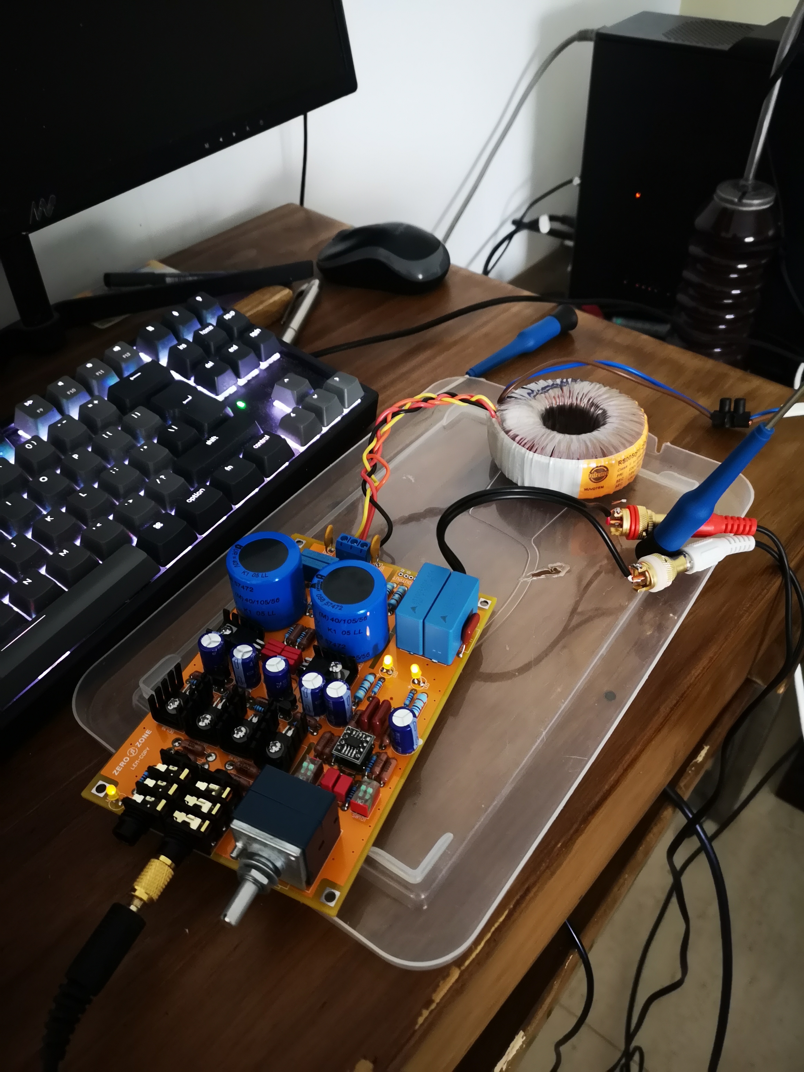
When I connected the Snubber (a 47nF paralleled with a 330Ohm resistor), I realized the PCB already has a pair of soldering pads connected to the transformers secondary and the Heat Fuses input.

So, now I´ve done some listening with my HD800, and this LBC amp works tremendously well - those headphone are now full bodied and not so sibilant as they were earlier, altough the SS3602 much treble! Regarding the Snubber mod, it seem´s to do very vell, as the amp are has a really black background and plenty of tight and deep bass, so I can really recommend this mod for this amp, as well as it can be used with every amp, DAC and CD-player etc with AC Voltage input. Do´nt forget to remove the four original 0,1uF cap´s for the rectifiers.

Except the Snubber mod, I´ve also done following below to reduce noise and EMF/EMI:

- Replaced the cheaper 1N400x with BYV27 (as they´re faster and with less noise, giving a cleaner Power to the Voltage Regulators).

- Connected a filter (from a PC´s Power Supply) at the Primary side at the transformer.

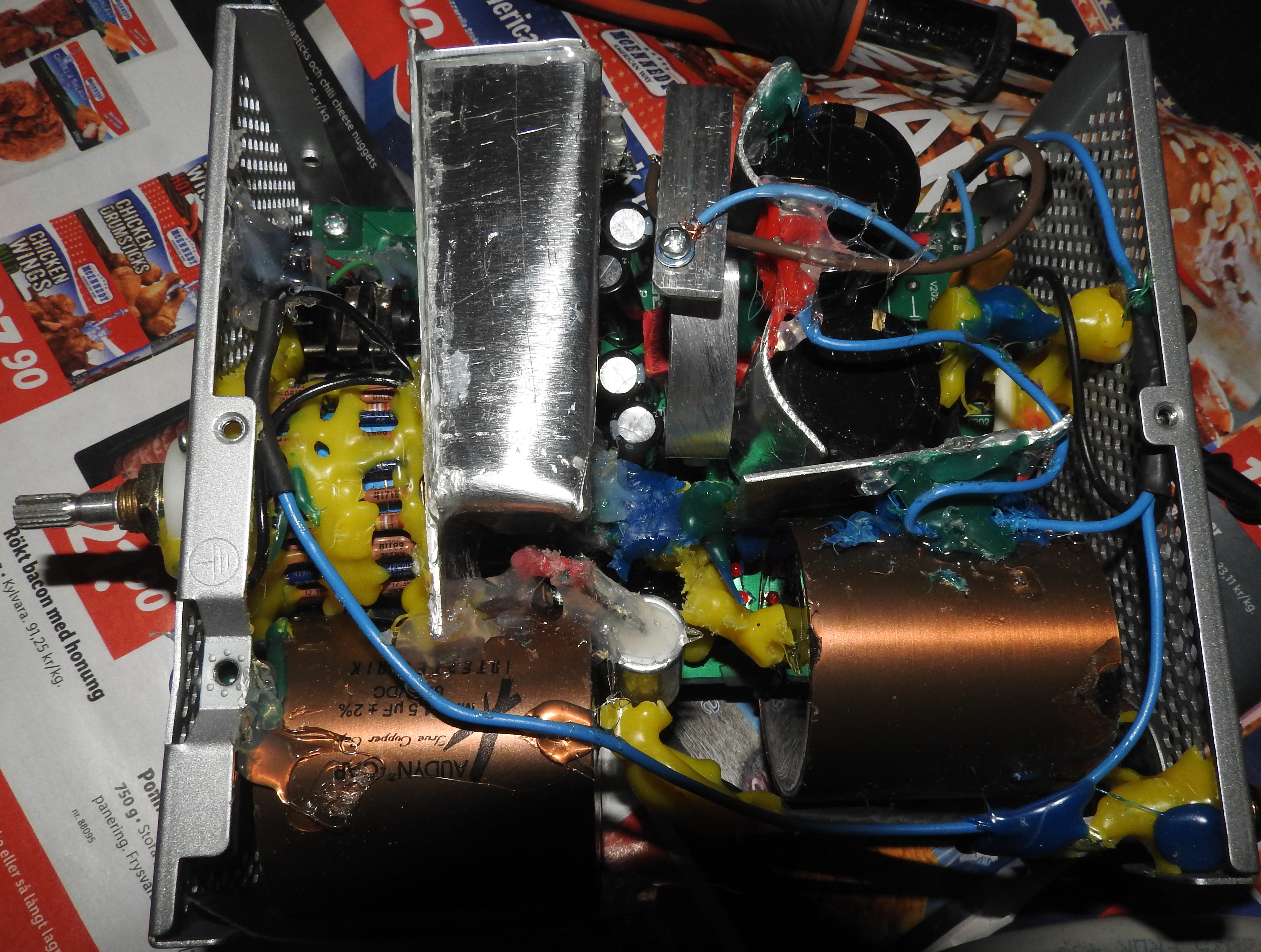
- Mounted some aluminium brackets inside the amp (connected to the enclosure) for less noise from neighbour components.

- Applied some glue or double sided rubber adhesive tape between PCB and caps to reduce vibrating movement for them.

- Mounted some caps underneath the PCB at the secondary side (mostly due to their big size, but this may also reduce some inteference from other components).

- Connected the Voltage regs heating plates to chassi enclosure (Silica sheet or similar must be used between the tabs and heating plates, when doing this!).

- Shielded the internal OFC signal cables and the cable between the transformer and amp, connected to chassi Earth.

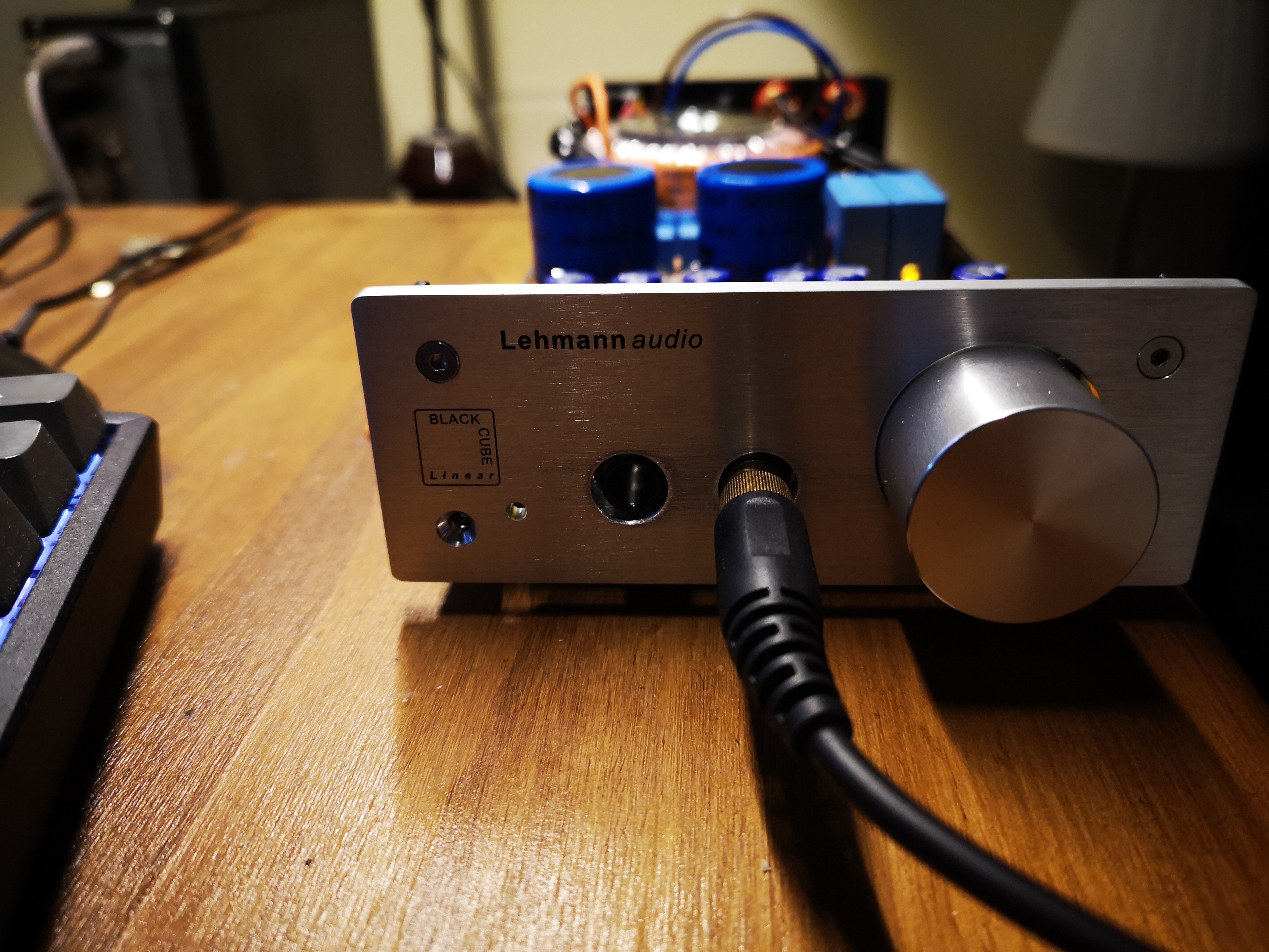
- Soldered the OpAmp directly to the PCB, without any socket (to avoid bad connection or oscillation from the PIN´s).

- Move the Toroid transformer out from the enclosure, in it´s own metal enclosure at a distance of about 8 inch.

- Connect the amp´s enclosure Earth to main wall outlet sockets Earth (if you have 3 PIN earthed wall outlets). This will help getting rid of any EMF/EMI noise and avoid letting it go towards the signal Earth that´s already separated with 1000pF cap and 100 Ohm resistor.


I will also add some rubber feet underneath the enclosure to minimize vibrations and a Ferrit bead to the high voltage cable, near the amp. And twisting the cables will also reduce EMF/EMI (at any direction; CW or CCW).

Snubber mod.jpg
Lovely Cube.jpg
 
Last edited:
Jul 19, 2020 at 5:47 AM Post #1,618 of 1,624
My LBC amp is working flawlessly perfect!


And as many people are worried about the amp are generating a lot of heat (mostly when used in BIAS Class A) and the enclosure has no ventilation holes, my solution about heat (sseen in the pictures above) was to use an aluminium plate to build a separate internal housing for the BD139/140 transistors, as those should generate most heat and will also benefit from higher temperatures than the other components.

For the outer enclosure, it has ventilation holes at the top to reduse heat to those.
 
Oct 18, 2020 at 1:06 PM Post #1,619 of 1,624
Hello friends.
Is there an updated Diy version of this Lehmann amp that doesn't need to be modified / repaired?

I am not good with Diy mods pcb so I look for something ready made that I can only buy on Aliexpress.

But I see that everyone always needs a repair or another for fake or non-standard parts.

What do you suggest?
 
Dec 6, 2020 at 9:25 AM Post #1,620 of 1,624
Most of the China clone kits at eBay/Aliexpress will have the cheapest components, I suppose that´s the reason many amps will fail or measure badly. They also use to have blue coloured PCBs. Many caps and resistors will not have the best quality or correct values, but should however work (for one that are not to choosey). For example, many caps are Polyester, that are no good for audio - at least they should be MKP Polypropylene, or even better Polysterene or Teflon (depending what area they´re used). But I think the most critical are the transistors BD139-10 and BD140-10, that in the original should be -16. And don´t forget the volume control attenuator, as it usually are of worst thinkable quality! For the original, it will have a 50K Ohm Alps "Blue Velvet", that are pretty nice. But replacing it for an stepped attenuator, will take it to another level! About the resistors, they should at least be 1% tolerance Metal film (but upgrading to for example Dale, Holco or PRP9372 copper models are even better!).
And the original LBC, are using OPA2134, while the clones will only have JRC/NE5532 (the cheapest one can think of!). There´s really many to choose among, and discretes will be the best and most expensives.

From start, I purchased some kits, and when I realized above, I began to replace more and more of the components. So later, I purchased some upgraded green PCBs of high quality (thicker copper) from eBay, and then added my ownprefered components/parts. It has since then been more and more modding to them, as seen in my modded schematic.

My latest recently upgrade, are to replace the SparkoS SS3602 for their SS2590 (the discretes OpAmp Pro model, that will cost ~50% more and are HUGE in size!).

So everything will depends on how much money you what to spend; For a cheap standard China-kit at ~$40, you should not expect too much (maybe it´s a bit better than the worst thinkable integrated headphone amps, used in low budgets receivers). For a complete set with hand picked components, that will be equal to the original BCL (with an MSRP at ~$15.000), it will cost you ~$200. If one decide to go all the way with an insanely upgraded amp (as I almost have), one should be prepared to pay at least $500.

So however how deciding, the cost should be quite a bargain, if having the "know how"! If not, please ask and we will help you - that´s why we´re using this forum!

Don´t hesitate to start the project, as long as you have at least some basic knowledge and tools such as an soldering iron. And I promise you will have fun and learn a lot on they way!
 

Users who are viewing this thread

Back
Top