The "Lovely Cube" Headphone Amp (Lehmann Black Cube Linear Clone)
Mar 6, 2015 at 8:17 AM Post #1,246 of 1,624
The LC "standard" toroid, the Telema 70063K, has a 2 x 15V output rated for 832mA each.
So, your R-core is a little short at 2 x 500ma. I would look for at least a 30VA.

Do you need both 9V and 15V outputs? There are many ebay listings for 30VA R-core with only 15V outputs.
http://www.ebay.com/itm/115V-230V-30W-R-Core-Transformer-15V-15V-for-Headphon-amp-preamp-/221703835182/

In regards to the mains filter, an R-core will give you some filtering. Better than a toroid. Adding the socket filter won't hurt but it's not a miracle if you have very noisy mains. I use a separate mains filter. Something like this http://www.tripplite.com/surge-protector-isobar-4-outlets-200v-240v-2m-cord-680-joule~EURO4/

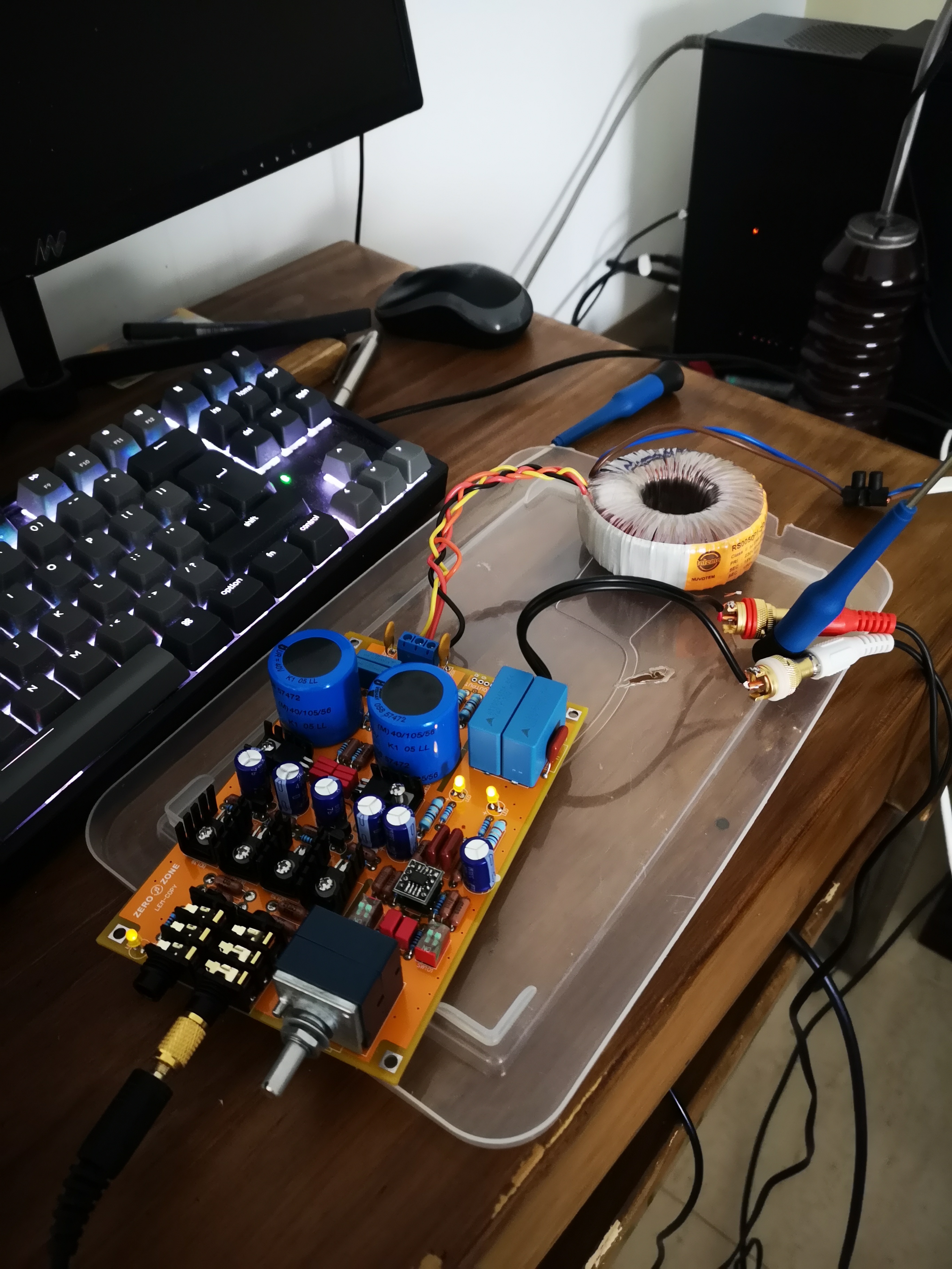
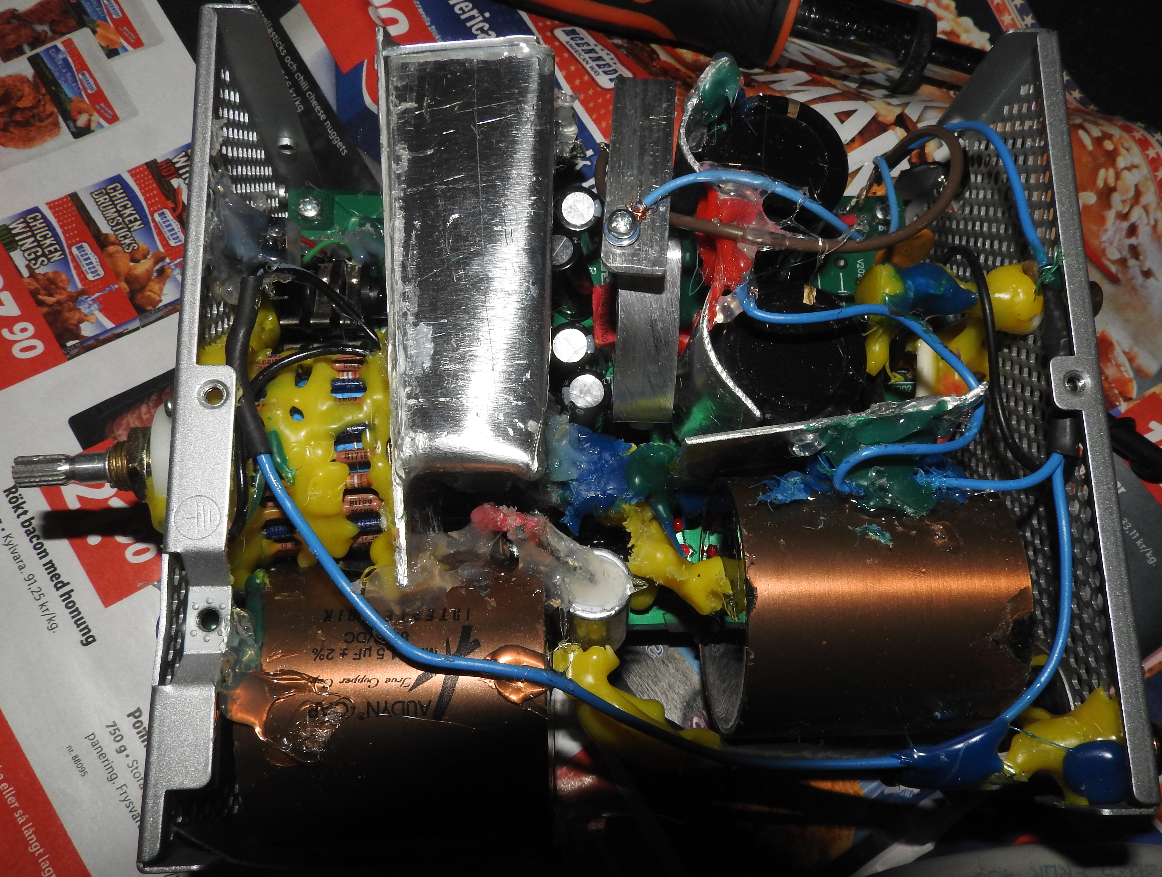
I have now get a toroid with 2 x 15V at 200VA, with a slow 2A fuse and then I installed an EMI-filter (like that one in the picture). I unmount the metal housing from it, and solder it directly at the wires and mounted everything in an power supply case for PC. I´m also gonna mount the LC in another power supply case, with a power cable between them (made for 115V/230V): http://www.8audio-mall.com/7-layers-triple-screens-cable-for-diy-audio-power-cable/
 
 
/ Mikael Markstrom
 
Mar 7, 2015 at 9:17 AM Post #1,247 of 1,624
Altough I´m not quite finished with the amp, I´m thinking of let my next LC be battery-driven for portable use.
 
This gonna let me skip all the components in the power supply, as I will connect the battery directly to the 15VDC  in (marked green).
 
Everything in the marked area below can be excluded; the heat fuses, rectifier diods, four caps, two filtering caps, resistor R301 - R304. But I guess the resistor R305 - R308 (includes the eventually Zener mod) must be left.
 
Am I right?


Mar 7, 2015 at 11:26 AM Post #1,248 of 1,624
Why do you want to use batteries?

What will happen when the battery drains down and the voltage goes below +15Vdc to the input of the LM317 regulator?

How will you supply -15Vdc to the input of the LM337 regulator?
 
Mar 7, 2015 at 11:51 AM Post #1,250 of 1,624
Why do you want to use batteries?

What will happen when the battery drains down and the voltage goes below +15Vdc to the input of the LM317 regulator?

How will you supply -15Vdc to the input of the LM337 regulator?

I have already done this with another amp, a Pro-Ject Headbox II, and it´s to make it portabel use with a FiiO X5 player, but this amp only had a LM317 - not 337.
When the battery drains out and the voltage are low, the sound will distort a lot and finally the sound level will be less.
 
I assume R305 - R308 will take care of the -15 to LM337, or am i getting wrong?
 
What are the 15VDC supposed for at LC? Is it to take get 15VDC out?
 
Mar 8, 2015 at 10:00 AM Post #1,252 of 1,624
I picked up my lovely cube today in Vietnam - really please with it - something that drives my he-400's decently

Here is my bedside setup

Lovely cube premium
Fiio e18
Moto x (source)
HE-400

Wife had a pair of hd598's running off the second output

 
Mar 9, 2015 at 11:52 PM Post #1,253 of 1,624
  I have already done this with another amp, a Pro-Ject Headbox II, and it´s to make it portabel use with a FiiO X5 player, but this amp only had a LM317 - not 337.
When the battery drains out and the voltage are low, the sound will distort a lot and finally the sound level will be less.
 
I assume R305 - R308 will take care of the -15 to LM337, or am i getting wrong?
 
What are the 15VDC supposed for at LC? Is it to take get 15VDC out?

 
I have no experience with this mod. Try it and let us know how it turns out. What type of battery are you planning on using to supply the 15V DC?
 
Mar 9, 2015 at 11:53 PM Post #1,254 of 1,624
I picked up my lovely cube today in Vietnam - really please with it - something that drives my he-400's decently

Here is my bedside setup

Lovely cube premium
Fiio e18
Moto x (source)
HE-400

Wife had a pair of hd598's running off the second output


Nice! So which of you have the control of the volume :)
 
Mar 13, 2015 at 12:14 PM Post #1,257 of 1,624
I have now asked a friend at my work about this project, as he is an old men with good know how in electrical - and he said it should be fine to drive the LC with battery connected after the rectifier diod´s. It will also be fine if connect the battery before the diod´s, but preferrable after (to 15VDC in).
 
But the two big 4700uF (or in my case 10000uF) filter cap´s should be used.
 
Mar 14, 2015 at 8:59 AM Post #1,258 of 1,624
When connecting the 2x15VAC to the PCB, which two cables should be connected together to get 0VAC?
 
In the LC diagram, it should be black and yellow. But when I measuring my toroid, I will get 0 Ohm between red-black and 0 Ohm between yellow-orange (as in the diagram), because those are connected in the same winding.
 
So, is this the right way to - should´nt it be black-orange connected together for 0VAC instead?
 
If connecting them wrong, I think it may generate some noise or interference to the power supply.

 
Mar 14, 2015 at 11:13 AM Post #1,259 of 1,624
When connecting the 2x15VAC to the PCB, which two cables should be connected together to get 0VAC?

In the LC diagram, it should be black and yellow.


Correct! It is wired in series and in phase. (But, I don't think it matters.)


But when I measuring my toroid, I will get 0 Ohm between red-black and 0 Ohm between yellow-orange (as in the diagram), because those are connected in the same winding.


Which toroid transformer do you have?

According to the Talema 91230-P2S2 datasheet:

The DC resistance of the two secondaries should be about 1.4488Ω each.
The DC resistance of the two primaries should be about 46Ω each.

Check your meter's ohm range setting.

What happened with your battery experiment?
 
Mar 15, 2015 at 5:06 AM Post #1,260 of 1,624
Correct! It is wired in series and in phase. (But, I don't think it matters.)
Which toroid transformer do you have?

According to the Talema 91230-P2S2 datasheet:

The DC resistance of the two secondaries should be about 1.4488Ω each.
The DC resistance of the two primaries should be about 46Ω each.

Check your meter's ohm range setting.

What happened with your battery experiment?

Thank´s for your reply, Tribbs!
 
I get the answer above from Stephen about this:
 
"Talema Toroid 30VA 2x15V has 2 version,  input 220V and input 115/230V version.  When using input 115/230V version for 220V input, the 2 primary coils must be connected in series, i.e. red , black-yellow, orange , to become 15-0-0-15V.  As I remember, the DC resistance across each primary coil is about 1.5 ohms. I attach here the pdf information about these 2 talema toroids."
 
So, I assume I should also connect black-yellow for 0V, red as 15V and orange as 15V altough I have the only 230V version with two primary wires? Am I correct?
 
There are 0 Ohm between red-black and 0 Ohm between yellow-orange. But no connection (infinity) between black-yellow. My DVM has autorange.
 
About the battery project, first I have to finished up my LC I´m now up with - gonna test it any day now as I´ve just received my last Holco resistors, then I may try it with battery.
Talema Toroid 30VA 2x15V has 2 version,  input 220V and input 115/230V version.  When using input 115/230V version for 220V input, the 2 primary coils must be connected in series, i.e. red , black-yellow, orange , to become 15-0-0-15V.  As I remember, the DC resistance across each primary coil is about 1.5 ohms. I attach here the pdf information about these 2 talema toroids.
 

Users who are viewing this thread

Back
Top