The DIY'rs Cookbook
Sep 30, 2020 at 3:25 PM Post #1,741 of 1,974
So the battle of the bands, er CCS's, has been raging with interesting results as we try different configurations and FET's in different configurations.

Right now as I type this I've just updated the primary bias adjustment CCS's, which sets the bias for both the driver and output tubes, using dual Supertex DN2540 DMOS FET's instead of using the 900v IXCP10M90S as the 'input' FET, and a 2540 as the 'output' FET.

Translated that means using the 2540's 'back to back' works better than mixing different FET's.
As long as the B+ is under ≈ 450VDC

The last experiment resulted in a very slow to reach full voltage and current setup, while this new approach has cut the 'settling time' down to ≈ 15-30minutes, down from 1-2 hours.

And so far it seems more stable and more 'linear', both of which are good signs.
But as usual it will take a few thermal cycles to see how well it all settles down, and then evaluate the results.

JJ

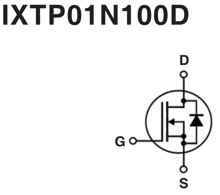
Give a try to a IXTP01N100D as the top device, those are really nice (but very expensive) depletion mosfets for that position. For the bottom device, give a try to the DN2540, IXTP01N100D, or even a BSS159 (best stats), in combo with the IXTP01N100D as the top.
 
Sep 30, 2020 at 7:24 PM Post #1,742 of 1,974
COOL!!!! :thumbsup::sunglasses:

Thanks for those suggestions, we'll look into them and I'll try those various combinations.

The DN2540 does seem to work well in both positions, at least for now, but the B+ feeding onto the CCS is ≈450VDC which is pushing the envelope a tad, so the longevity of that top DMOS FET may be a 'problem' in the long run.

MOAR EXPERIMENTS!!!!

JJ :ksc75smile:
 
Sep 30, 2020 at 8:07 PM Post #1,743 of 1,974
So unless I'm missing something the BSS159 is rated for 60vdc so it would be a source of smoke and perhaps a sharp retort at turn on… :scream:
hahahahahahahahahaha :ksc75smile:

JJ :thumbsup:
 
Sep 30, 2020 at 9:39 PM Post #1,744 of 1,974
So unless I'm missing something the BSS159 is rated for 60vdc so it would be a source of smoke and perhaps a sharp retort at turn on… :scream:
hahahahahahahahahaha :ksc75smile:

JJ :thumbsup:

You would only use it as the bottom device or in a really low voltage tube amp.

Remember that 90+ percent of the voltage drop from B+ down to plate voltage happens on the top device. The bottom device is only seeing a handful of volts (somewhere in the single digits to mid teens) which is why the capacitance of the bottom device is always such a problem. The smaller the voltage drop across a mosfet is, the larger it's apparent gate capacitance is.

The easiest way to think about it is that the bottom device is really only acting as a gain multiplier.
 
Last edited:
Sep 30, 2020 at 10:17 PM Post #1,745 of 1,974
So using different words, the 'input' FET knocks the B+ voltage down to 'useable' levels, and the lower 'output' FET supplies the desired current which in turn dials in the voltage for the load (in this case the plate).

But it seems to me that using the BSS159 would still let the magic smoke out during the turn on surge, where the CCS output voltage swings from ≈40vdc to 400+vdc across the output tube, on it's way to the 170vdc target voltage, albeit the peak HV spikes are fairly short in duration.

And I still have to wonder if the rather small amount of current these devices are being used at, is a 'cause' of instability or 'non-linear' behavior just in and of itself, especially in a operationally dynamic 'complex(LRC)' audio circuit. :thinking:

Just passing thoughts that rattle around in my head… :face_palm:

JJ
 
Last edited:
Sep 30, 2020 at 10:58 PM Post #1,746 of 1,974
So using different words, the 'input' FET knocks the B+ voltage down to 'useable' levels, and the lower 'output' FET supplies the desired current which in turn dials in the voltage for the load (in this case the plate).

But it seems to me that using the BSS159 would still let the magic smoke out during the turn on surge, where the CCS output voltage swings from ≈40vdc to 400+vdc across the output tube, on it's way to the 170vdc target voltage, albeit the peak HV spikes are fairly short in duration.

And I still have to wonder if the rather small amount of current these devices are being used at, is a 'cause' of instability or 'non-linear' behavior just in and of itself, especially in a operationally dynamic 'complex(LRC)' audio circuit. :thinking:

Just passing thoughts that rattle around in my head… :face_palm:

JJ

The bottom device in a CCS cascode will only see 1-5 volts during typical operation. The top FET will drop the B+ voltage down to a voltage approx 1-5V higher than what will be seen at the source of the bottom device. How do you know how many volts will appear across the bottom FET? The bottom FET sets the current, and the voltage that the top device develops across it is determined by the "output characteristics" graph for that particular top mosfet. So say you have the BSS159 as the bottom device and set the source resistor on the BSS159 such that it sets the current at 10mA, and you use the IXTP01N100D as the top device (output characteristics graph below), that means that to have 10mA flowing through the IXTP01N100D it has to develop a voltage of approx 2.1V across the BSS159 (2.1V from the BSS159 drain to source). This 2.1V is the gate-to-source voltage (on the IXTP01N100D) necessary for the IXTP01N100D to maintain the 10mA.

1601520321953.png


So you may ask: how does the bottom device set the voltage at the anode of the tube? The bottom device essentially just lets the voltage of the tube rise up to the point that there is the 10mA flowing across it (or whatever current you set).

If you scour a bunch of datasheets for all the available depletion mode mosfets and find their capacitance at 2.1V drain-to-source, the BSS159 is one of the lowest you will find that is capable of supplying large amounts of current (up to 80+mA). There are some depletion FETs with even lower capacitance for very low currents under 2mA (such as the LND150). Unfortunately the BSS159 is only in SOT-23 package, so you have to deal with the SMD component mounting, but it's otherwise a very good device stat wise.
 
Sep 30, 2020 at 11:33 PM Post #1,748 of 1,974
So using different words, the 'input' FET knocks the B+ voltage down to 'useable' levels, and the lower 'output' FET supplies the desired current which in turn dials in the voltage for the load (in this case the plate).

But it seems to me that using the BSS159 would still let the magic smoke out during the turn on surge, where the CCS output voltage swings from ≈40vdc to 400+vdc across the output tube, on it's way to the 170vdc target voltage, albeit the peak HV spikes are fairly short in duration.

And I still have to wonder if the rather small amount of current these devices are being used at, is a 'cause' of instability or 'non-linear' behavior just in and of itself, especially in a operationally dynamic 'complex(LRC)' audio circuit. :thinking:

Just passing thoughts that rattle around in my head… :face_palm:

JJ

It really shouldn't affect the bottom fet. Im sure there is some odd ball scenario where the turn on surge would kill the bottom fet, but I would have to imagine that what ever would kill the bottom fet would have to kill the top fet first.
 
Oct 1, 2020 at 12:32 AM Post #1,750 of 1,974
@A2029

Just so you have a clearer picture of what is going on, here is the schematic. It started off as a fairly simple build, but became sort of a Frankenstein build.

This is the response of the voltage on the 71a plate inside of LTspice. Somehow what john is experiencing is the inverse of this graph. In real life the voltage starts off very low and gradually builds up over 30min to an hour. Very strange.

As John has pointed out, we have already tried a number of different CCS solutions. Nothing seems to help.


head-fi ccs issue.png
 
Oct 1, 2020 at 12:43 AM Post #1,751 of 1,974
@A2029

Just so you have a clearer picture of what is going on, here is the schematic. It started off as a fairly simple build, but became sort of a Frankenstein build.

This is the response of the voltage on the 71a plate inside of LTspice. Somehow what john is experiencing is the inverse of this graph. In real life the voltage starts off very low and gradually builds up over 30min to an hour. Very strange.

As John has pointed out, we have already tried a number of different CCS solutions. Nothing seems to help.


head-fi ccs issue.png

Thanks Tjj226, I hadn't really been following this thread closely, but when I saw the post on CCS rolling I jumped in. This gives much better background. Can you send me the .asc file for this sim?

@johnjen Where are you measuring the voltage rise over time? Plate? How much does the voltage rise over time? Where does it start, where does it end? Does it ever stabilize at a certain voltage?

Sorry if these were answered previously, just not sure how many pages back in the thread to go
 
Oct 1, 2020 at 12:47 AM Post #1,752 of 1,974
Thanks, A2029!
That detailed explanation of the inner workings of these CCS's is most helpful.
That helps me (and I would assume others) understand what and where the voltages are located inside the CCS and tells me why the 'output' FET runs cool and the 'input' FET HAS to use a heat sink, mostly due to the voltage drop each FET deals with.

I caught that the "BSS159 is only in SOT-23 package" and thought that I could most likely 'adapt' a perf board and 'make it work', one way or another.
But I may have to pay close attention to the pad size and spacing etc, so that they match up, more or less.

And now to commence with even more head scratching…
hahahahahahaha

JJ :ksc75smile:
 
Oct 1, 2020 at 12:56 AM Post #1,753 of 1,974
Thanks Tjj226, I hadn't really been following this thread closely, but when I saw the post on CCS rolling I jumped in. This gives much better background. Can you send me the .asc file for this sim?

@johnjen Where are you measuring the voltage rise over time? Plate? How much does the voltage rise over time? Where does it start, where does it end? Does it ever stabilize at a certain voltage?

Sorry if these were answered previously, just not sure how many pages back in the thread to go

Pmed you with the .asc file.

Hopefully John will reply with a more a more detailed response about what is going on than what I can tell you. I built this amp for John a while ago, but we have been playing around with modifications and other experiments. We live in different states, so this process has been a long game of telephone.

The good news is that the CCS actually does provide a big sonic improvement over the choke we had in there originally. Bad news is it may or may not be causing this voltage instability issue.

Its also worth pointing out that at this point the 71a amp is more of a research project to find out what does and doesn't work. The main goal is to see how well we can control the audio path. It's not like we are under the gun to fix this amp like we would be if this were johns only amp. But it sure would be nice to figure out what in the schiit is going on : P
 
Oct 1, 2020 at 1:04 AM Post #1,754 of 1,974
@johnjen Where are you measuring the voltage rise over time? Plate? How much does the voltage rise over time? Where does it start, where does it end? Does it ever stabilize at a certain voltage?

Sorry if these were answered previously, just not sure how many pages back in the thread to go
When power is turned on the voltage rises quickly (1-2 seconds) to 400+ volts, then drops down to ≈ 250vdc, and hangs for ≈ 1 second.
It then drops down to ≈ 40vdc and sorta quickly rises to ≈ 120-30 volts within ≈ 30sec after startup.
From there it continues to even more slowly rise to the peak of 170vdc after 1-2 hrs where it 'stabilizes' with a swing of ±5vdc.

These voltages are across the tube (plate to cathode).

The odd thing is I did try to use the IXCP10M90S as the input and output FET and it didn't work at all, as in it went completely sideways.
When I changed to using the 2540 as the output FET it went back to 'normal' operation.

Currently I'm back to using dual 2540's as both the input and output FETs.

Thanks for your curiosity and looking into all of this.

Oh and there is a minor difference between the above schematic and the 'as built' in that there are 1KΩ resistors (not the 330Ω as listed in the schematic below) so no direct connections for where R2/R6 & R5/R7 are used as shown above.
And no 1Ω current sense resistors (R3) used in my CCS's either.
HP-CCS.jpg

ps Oh and the SQ is stunning as in it fully captures my attention and won't let go.
I mention this because despite it's 'faults' etc it delivers an acoustic presence that is simply captivating.

JJ
 
Last edited:
Oct 1, 2020 at 1:59 AM Post #1,755 of 1,974
When power is turned on the voltage rises quickly (1-2 seconds) to 400+ volts, then drops down to ≈ 250vdc, and hangs for ≈ 1 second.
It then drops down to ≈ 40vdc and sorta quickly rises to ≈ 120-30 volts within ≈ 30sec after startup.
From there it continues to even more slowly rise to the peak of 170vdc after 1-2 hrs where it 'stabilizes' with a swing of ±5vdc.

Ah, okay, I believe this all makes sense.

Let's look at the 6BQ7A tube first: When you power up, the heater is cold, and the cathode is cold, so no emission from the cathode. For the CCS above this tube, the bottom FET essentially just keeps letting the voltage rise as it is trying to source the current from the tube. But no amount of voltage will get that current from a cold tube, so the voltage on the plate of the 6BQ7A will likely rise up to near the B+ voltage on turn on.

Same thing happens on the 71A tube, the cathode is cold so there is no emission as the CCS tries to pull ~20mA from the tube. The CCS keeps raising the voltage more and more as it attempts to source its 20mA. This will peg the voltage at 400+ volts at the start. As the 71A heats up, it starts to conduct, which means that the bottom FET drops the voltage down to 250v as that is the voltage pulling 20mA through the tube. As the cathode of the 71A heats more its cathode emission increases sharply. The voltage on the 71A grid may still be very elevated if the 6BQ7A is slower to reach its threshold heat for high emission (i.e. the voltage on the plate of the 6BQ7A will only come down when there is enough emission from the 6BQ7A cathode in order to pull the bias current at a lower plate voltage). For the 71A with a grid that is positive respective of the cathode, the CCS over the 71A drops the voltage way down to 40v as that is all that it takes to source 20mA from the tube with a high grid voltage that hasn't settled.

It is shortly after this point that the 6BQ7A really starts to increase its cathode emission. As it increases its cathode emission, the voltage at the 6BQ7A plate drops as there is less voltage required to pull the bias current through the 6BQ7A tube. The plate voltage drop of the 6BQ7A means that the grid voltage of the 71A is also dropping. As it drops, the CCS above the 71A needs to increase the 71A plate voltage from the low 40v's in order to pull the 20mA from the tube. The voltage then quickly rises to 120-130v.

The continuation of the rise to 170V across the 71A is a result of the 6BQ7A slowly continuing to increase in emission from its cathode over time, and as it does so the 6BQ7A plate voltage will slowly fall as less voltage at the 6BQ7A plate is needed in order to pull the bias current. Slowly reducing 71A grid voltage means slowly increasing 71A plate voltage in order to continue pulling the 20mA through the tube.


Hope that all makes sense. So all in all nothing to worry about imo. The only concerns would be in making sure that the grid to cathode max voltage doesn't get exceeded at any point for the 71A if there is one (I haven't looked) as there is likely 400V between the grid and cathode at first turn on. You've run the amp tho and no sparks so I believe you should be good. Just a matter of letting the amp warm up for a couple of hours, then dialing in your voltages to wherever you want them, and you should be good to go.
 
Last edited:

Users who are viewing this thread

Back
Top