The Apple diyMod: My Take on the Famous iMod [56k killer] Featuring 3G, 4G, 5G and nano 1G!
Jan 26, 2008 at 7:44 PM Post #796 of 3,220
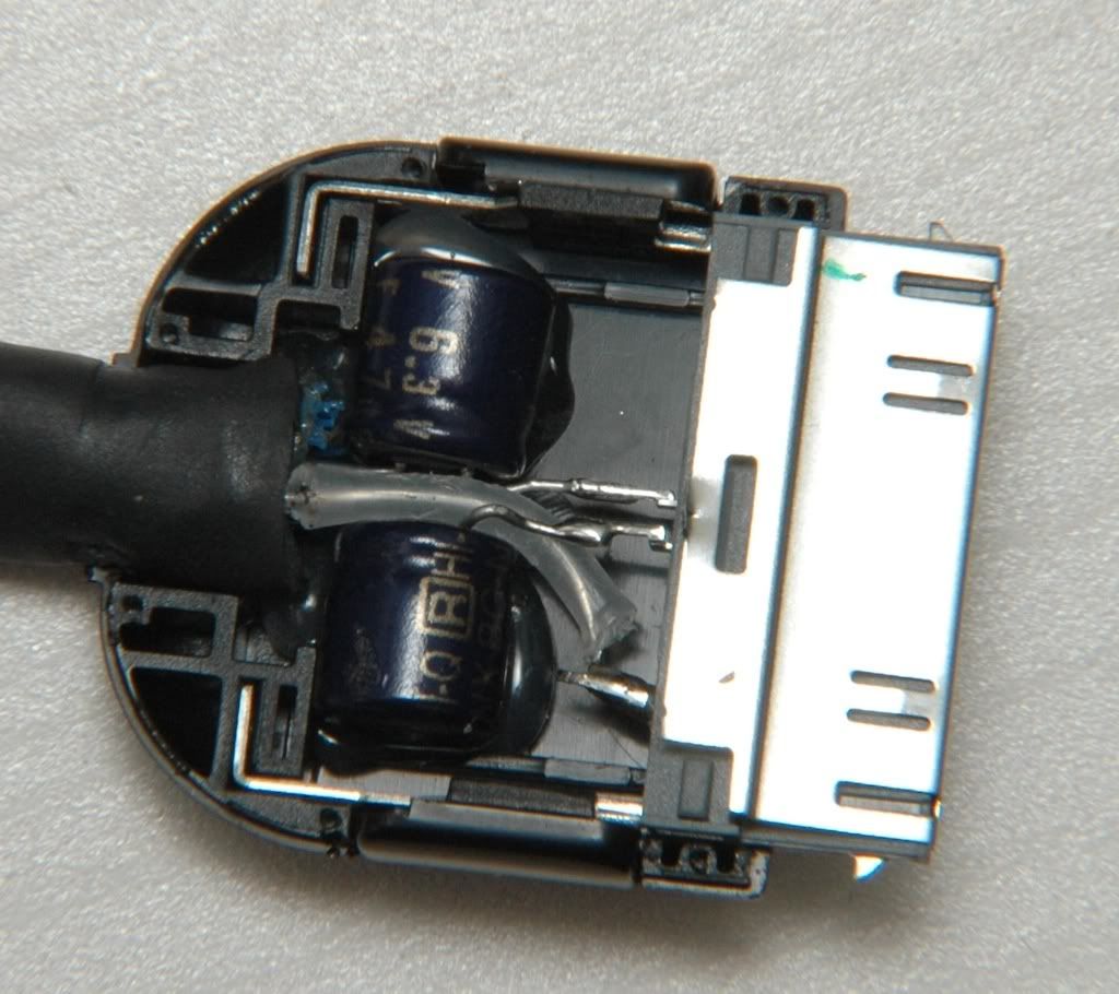
guys, please...i need your opinion, i made lod for my DIYmod nano right now...i've made mini to mini interconnect + dock with female jack, here's the picts of it...

2000237652489003211_rs.jpg


2000265832334092805_rs.jpg


is it a good idea ? what i want is 1 dock for every cable that i need...i'll make another interconnect cables, like mini to RCA, mini to big jack and so on...
tongue.gif
 
Jan 26, 2008 at 11:02 PM Post #798 of 3,220
Thats your choice iQEM. Some around may say that it is just more connections but it probably wont make that huge of a difference. I personally like to avoid doing that sort of thing if possible, but it really is up to you.
 
Jan 26, 2008 at 11:05 PM Post #799 of 3,220
iQEM: I think so, I mean, some may try use as little connections as possible, but I really dont think it would make a huge difference unless with a very revealing system. naturally, try keep things built well with decent wire and stuff, and you should be good. If I may make a recommendation though: placement and routing are very important. I think you should place the caps in a way that suit their physical environment, and bend their leads in perfect rout. maybe figure out the best placement, bend the leads to be in the perfect positions, glue the caps in place, everything should be solid for a good long time. also, use some heat shrink in there, it'll keep things neat and the shorts away. take a look here to see what I mean:
 
Jan 26, 2008 at 11:56 PM Post #800 of 3,220
looking good iQEM

it looks like a really tight fit with the BGs and female jack. Plus it looks like if you press hard on the jack it might disturb the BGs. You could just give up the idea of a completely internal female jack and go with one that is slightly external.

Like ipod connector -> BG -> wires -> very short external female jack/ This way you won't put pressure on the BGs. Just my opinion.
 
Jan 27, 2008 at 4:51 AM Post #801 of 3,220
Here's my removal of the Resistors.

Looks like the I went a little too far on the one, but I don't think I need that side anyways...=)

This is for Ipod 4G Photo..
dscf4104copycr0.jpg


Can't really see it that well...I'll try another pic/angle


Edit:

Here we are..
dscf4105copyio4.jpg


I tested the resistance @ each of the 4 pts using pin #14 on the Wolfson chip as ground (labeled AGND on data sheet).


When I put the positive end of my DMM on the "south" end of the closeup image from ipodlinux, with my DMM set to the 2000kΩ position, I get a reading around 600kΩ, for both south ends of each spot. When I move to the "north" end, I get a reading around 160kΩ on the same setting (2000kΩ).
Does the "higher" reading of the "south end" mean that that is where I should solder my wire to for the mod? I feel pretty confident that it is, but would like to double check.. Thanks!
 
Jan 27, 2008 at 5:28 AM Post #802 of 3,220
Good work, iQEM and BrinNutz. Even at this stage of the project, it's great to still people making progress with their diyMods.
smily_headphones1.gif


iQEM:

Why not go with a dock connector with mini connector out? I'd just skip the female jack altogether, but that's just me. When you use the mini jack and the mini-mini cord (with F12s of all connectors), you increase the chance of damaging your dock. There's more torque acting on the dock, so that's something you have to consider if you keep this setup. My advice is either remove the female jack or order a smaller one. fordgtlover made an iPod connector and it fit okay, though he didn't have Black Gates in it. I don't know which mini female jack he uses, but maybe someone else here will recognize it, or you can PM him.

cfcubed:

Adding disclaimer/warning now...
 
Jan 27, 2008 at 5:37 AM Post #803 of 3,220
Quote:

Originally Posted by cfcubed /img/forum/go_quote.gif
Not to offend anyone, and this is just IMHO of course, but a DIYmod probably does not make a good first project of this sort. I'd expect one to be quite handy w/a soldering iron & have at least a couple builds of some kind under their belt before attempting this. At least maybe practice on a junker PCB w/SMD parts... Combing through this thread & that of similarly intricate projects shows what can go (horribly?) wrong.

Again, just an opinion & sure if one has a sacrificial ipod, or one already having issues, and wants a challenge/adventure - whatever. But if someone wants a DIYmod, has the resources but doesn't want the risk assoc w/doing one, there may be builders around willing to assist directly w/the work (other than myself at the moment
smily_headphones1.gif


I hear ya...But....This is my first time, with a soldering iron, I don't think I did too horribly bad!

Quote:

Originally Posted by joneeboi /img/forum/go_quote.gif
Good work, iQEM and BrinNutz. Even at this stage of the project, it's great to still people making progress with their diyMods.
smily_headphones1.gif


Thanks, hope I didn't do too bad!!
 
Jan 27, 2008 at 5:43 AM Post #804 of 3,220
Quote:

Originally Posted by BrinNutz /img/forum/go_quote.gif
I tested the resistance @ each of the 4 pts using pin #14 on the Wolfson chip as ground (labeled AGND on data sheet).


When I put the positive end of my DMM on the "south" end of the closeup image from ipodlinux, with my DMM set to the 2000kΩ position, I get a reading around 600kΩ, for both south ends of each spot. When I move to the "north" end, I get a reading around 160kΩ on the same setting (2000kΩ).
Does the "higher" reading of the "south end" mean that that is where I should solder my wire to for the mod? I feel pretty confident that it is, but would like to double check.. Thanks!


If the south end of the resistors read any resistance, then they aren't necessarily connected to the same ground as pin 14 (I'm not sure all the ground planes are connected to each other). Another check you can do is checking the voltage of the south end of the resistors relative to pin 14 with the iPod switched on. If they have the same voltage, then you can be fairly certain that it is ground. Either way, what you should have been checking this whole time was continuity between the audio pins and the south pads, not between them and AGND at pin 14. If they have 0 ohms, then you grab the signals from those pads. A simpler way of doing that is soldering wires straight to the Wolfson DAC, but not everyone believes in doing things the simple way.
biggrin.gif
What strange people we all are.
 
Jan 27, 2008 at 6:11 AM Post #805 of 3,220
Quote:

Originally Posted by joneeboi /img/forum/go_quote.gif
If the south end of the resistors read any resistance, then they aren't necessarily connected to the same ground as pin 14 (I'm not sure all the ground planes are connected to each other). Another check you can do is checking the voltage of the south end of the resistors relative to pin 14 with the iPod switched on. If they have the same voltage, then you can be fairly certain that it is ground. Either way, what you should have been checking this whole time was continuity between the audio pins and the south pads, not between them and AGND at pin 14. If they have 0 ohms, then you grab the signals from those pads. A simpler way of doing that is soldering wires straight to the Wolfson DAC, but not everyone believes in doing things the simple way.
biggrin.gif
What strange people we all are.


I understand now.

But with the setting still @ 2000kΩ the lowest I get on both south end when connected to each respective audio terminal @ the headphone jack is about 180kΩ.

When connected to the north terminal and each respective audio terminal @ the headphone jack I'm reading about 600kΩ.

Is it safe to assume that the the 180kΩ is supposed to be 0kΩ or it's close enough that it could just be the error on the DMM? (Accuracy according to the manual is +/- 1.0% reading + 2 digits on the 2000kΩ setting).
 
Jan 27, 2008 at 6:31 AM Post #806 of 3,220
Quote:

Originally Posted by wgr73 /img/forum/go_quote.gif
Thats your choice iQEM. Some around may say that it is just more connections but it probably wont make that huge of a difference. I personally like to avoid doing that sort of thing if possible, but it really is up to you.


i c, thax for your input mate...
wink.gif


Quote:

Originally Posted by ruZZ.il /img/forum/go_quote.gif
iQEM: I think so, I mean, some may try use as little connections as possible, but I really dont think it would make a huge difference unless with a very revealing system. naturally, try keep things built well with decent wire and stuff, and you should be good. If I may make a recommendation though: placement and routing are very important. I think you should place the caps in a way that suit their physical environment, and bend their leads in perfect rout. maybe figure out the best placement, bend the leads to be in the perfect positions, glue the caps in place, everything should be solid for a good long time. also, use some heat shrink in there, it'll keep things neat and the shorts away. take a look here to see what I mean:


well, i'm not finish yet though..still figure out what most suite with my needs, and yes i plan to do as nicests as you dock too but using female jack...after i finish testing on the lod i'll seal the dock body with glue so the caps unharm in place, and the female jack too...but thx for reminding me for those awesome dock of yours...
wink.gif


Quote:

Originally Posted by CAvanessia /img/forum/go_quote.gif
looking good iQEM

it looks like a really tight fit with the BGs and female jack. Plus it looks like if you press hard on the jack it might disturb the BGs. You could just give up the idea of a completely internal female jack and go with one that is slightly external.

Like ipod connector -> BG -> wires -> very short external female jack/ This way you won't put pressure on the BGs. Just my opinion.


well i can place the female more front than before and seal with with glue, is it a good idea ?
confused.gif


Quote:

Originally Posted by joneeboi /img/forum/go_quote.gif
Good work, iQEM and BrinNutz. Even at this stage of the project, it's great to still people making progress with their diyMods.
smily_headphones1.gif


iQEM:

Why not go with a dock connector with mini connector out? I'd just skip the female jack altogether, but that's just me. When you use the mini jack and the mini-mini cord (with F12s of all connectors), you increase the chance of damaging your dock. There's more torque acting on the dock, so that's something you have to consider if you keep this setup. My advice is either remove the female jack or order a smaller one. fordgtlover made an iPod connector and it fit okay, though he didn't have Black Gates in it. I don't know which mini female jack he uses, but maybe someone else here will recognize it, or you can PM him.


i pick those metode cos' i haven't got headamp of my own right now, i thought it would more usefull IF i make the lod like that...so i can use whatever cable that i need/want, fyi i made a cable mini to RCA as well...is it too risk to do that instead of using 1 dock for each cable i made ?
confused.gif
 
Jan 27, 2008 at 6:33 AM Post #807 of 3,220
Quote:

Originally Posted by BrinNutz /img/forum/go_quote.gif
.....
Is it safe to assume that the the 180kΩ is supposed to be 0kΩ or it's close enough that it could just be the error on the DMM? (Accuracy according to the manual is +/- 1.0% reading + 2 digits on the 2000kΩ setting).


Not really. its safe to say that a short may measure as a few singleohms, mostly the resistance of the DMM wires, etc. With error and all, it would still show up as 0KΩ on that scale. Though, I'm not sure what you're meant to be measuring cause I haven't followed your specific mod/ipod. Though like joneeboi's mentioned, if you're looking for the spot to solder the L/R wire too then I'd suspect you should be looking for the DACs L/R out too (maybe on a more sensitive scale). But for a first project, you've come a long way! and to have RTFM of you DMM.. kudos! I think I neglected to read mine till about 6 years in.. keep us updated!


Quote:

Originally Posted by iQEM /img/forum/go_quote.gif
....
well i can place the female more front than before and seal with with glue, is it a good idea ?...


I think a good point has come up here regarding strain relief that shouldn't be neglected. I'd thought maybe using a little lead with a normal female at the end would be a decent idea, but that was just for stuffing sake, IMHO, the strain relief is more of an issue, and worth mentioning, again. When you get yourself a little amp for the go, you can always build yourself another more fitting DOCK.
 
Jan 27, 2008 at 6:33 AM Post #808 of 3,220
Interesting. Maybe you're going to have to solder to the chip after all.
biggrin.gif
Follow the copper traces out of the chip and see where they go. That'd be the easiest alternative. I suppose it isn't so bad sending the signal to those resistor spots, but it'd be better to keep the signal path simple and to put only relatively high quality parts in the signal path.
 
Jan 27, 2008 at 6:53 AM Post #809 of 3,220
ruZZ,
Thanks!

jon,
There are no copper traces out of the chip on my PCB anywhere.

See:
dscf4104copycr0.jpg


I guess I could do a trial and error with the resistor pads. The soldering directly to the chip probably isn't an option. there's not a chance in hell I could do that. Simply because I cannot test pin 12 on the Wolfson which says it's "ROUT1" or "ROUT2" because I have to have the headphone jack PCB plugged in and my testers for the DMM are just a little to fat where they come together, so that's out of the question as far as testing that circuit goes.

But I don't have anywhere to actually solder to the Wolfson anyways.
 
Jan 27, 2008 at 1:01 PM Post #810 of 3,220
Quote:

Originally Posted by BrinNutz /img/forum/go_quote.gif
I hear ya...But....This is my first time, with a soldering iron, I don't think I did too horribly bad!

Thanks, hope I didn't do too bad!!


Hey BrinNutz, although some of your posts *may* have tipped the scales thinking I had to post what I did, it was more of a general comment. There has been some iPod carnage around these parts
smily_headphones1.gif


I've been soldering & burning fingers almost since the 1st Moon landing & still SMD work gives me the willies (& even couple toasted AD8397s from my Mini³ build). Thought the idea of practicing on a junker PCB w/SMDs might help someone....

Your work looks o.k. to me so far (you do have some fun left tho
smily_headphones1.gif

Good luck & have fun!

joneeboi - You did have big warnings in the OP as I recall... And if one reads through things they get the point. You have a great thread going here that I'm sure a lot of people appreciate!
 

Users who are viewing this thread

Back
Top