The Apple diyMod: My Take on the Famous iMod [56k killer] Featuring 3G, 4G, 5G and nano 1G!
Nov 30, 2007 at 6:04 AM Post #31 of 3,220
Quote:

Originally Posted by iQEM /img/forum/go_quote.gif
@ joneeboi:
just curious, one wire go to capacitor and the other one go to ... ?! and what the capacitor that you've used looks like ?


To be painfully clear, it goes from from LOUT1 or LOUT2 to the positive lead of the capacitor and from the negative lead to the output jack's left channel. From ROUT1/2 to the positive end of the cap, then negative to the output's right channel. Ground goes to ground, but not all grounds will work. Use the poke-and-listen technique and things should go fine. Anyone step in and correct me if the P-A-L system can damage the player.

[Okay, maybe going P-A-L is pretty dumb. Just to be safe, one should try to keep the jack's ground to this area if possible. It's already a pretty busy area sitting behind the LCD screen, but I'm sure you DIYers can figure something out.

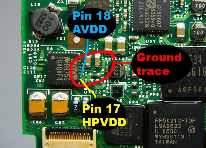
See if a big blob of solder and some wire can be applied to this portion. Both of pins 17 and 18 are the analogue supply, albeit AVDD is just cited as the analogue supply and HPVDD is the supply for R/LOUT1/2 and also MONOUT which is pin 10, but that's irrelevant. It seems as though you could easily solder a wire here. I used navships 30AWG Teflon-coated 7 strand SPC, so it was a bit easier to fit things for me. For the nano, I'm not sure how it'll work. Pictures would be great though, wgr73.

nano21.jpg
]

[[I really shouldn't post this late at night. The ground doesn't extend as far as the red ellipse suggests. It flows out from the two pins on the WM8975, goes to the two yellow capacitors, then it hits that black bit, which I think is an inductor. Just to clarify.]]
 
Nov 30, 2007 at 12:03 PM Post #32 of 3,220
Ok, this is all great, but ..... if you can tap into the signal after the DAC, and if your going to have an external enclosure anyway..... could you tap into the signal BEFORE the DAC and use the external space to convert to optical or coax digital out? Now that would be AWESOME. A resonabely good protable player that could link directly into a home setup as a true source as well!
 
Nov 30, 2007 at 3:23 PM Post #33 of 3,220
I had already thought about this, but I'm not sure what you would be connecting to inside the iPod to send to the DAC. As far as I understand coaxial cables, they're just two wires, one sending and the other returning electrons. You'd have to tell from the WM8975/8971's schematic and pinout to see what needs to happen.

According to the datasheet,

pin 1 is the master clock
pin 2 is the digital core supply
pin 3 is the digital buffer (i/o) supply
pin 4 is the digital ground (return path for both pin 2 and pin 3)
pin 5 is the audio interface bit clock
pin 6 is the DAC digital audio data
pin 7 is the audio interface left/right clock/clock out

I don't really know what this all means, so you digital audio fanatics are going to have to decipher this.
 
Nov 30, 2007 at 3:54 PM Post #34 of 3,220
Quote:

Originally Posted by AKChastain /img/forum/go_quote.gif
Ok, this is all great, but ..... if you can tap into the signal after the DAC, and if your going to have an external enclosure anyway..... could you tap into the signal BEFORE the DAC and use the external space to convert to optical or coax digital out? Now that would be AWESOME. A resonabely good protable player that could link directly into a home setup as a true source as well!


It was discussed not ones. Here one of the threads about it:

http://www.head-fi.org/forums/f6/wou...al-out-249755/
 
Nov 30, 2007 at 5:04 PM Post #35 of 3,220
What about tapping into the source BEFORE the DAC and adding a switch so you can use a home DAC when at home and make it still able to use as a portable. I mean, if you have a tic tack box on the back why not put a slightly bigger box on there since the footprint is still the size of the iPod itself. You wouldn't lose any portability, and still have the option to be able to use it as normal. Also, with the slightly larger box on the back, you could add your optical outs, etc.

Then again, that might be a bit much, lol.
 
Nov 30, 2007 at 6:18 PM Post #36 of 3,220
Quote:

Originally Posted by oicdn /img/forum/go_quote.gif
What about tapping into the source BEFORE the DAC and adding a switch so you can use a home DAC when at home and make it still able to use as a portable. I mean, if you have a tic tack box on the back why not put a slightly bigger box on there since the footprint is still the size of the iPod itself. You wouldn't lose any portability, and still have the option to be able to use it as normal. Also, with the slightly larger box on the back, you could add your optical outs, etc.

Then again, that might be a bit much, lol.


The answer is in post 8 of the thread recommended above. Nobody knows the internal type of signal. Apple's not going to tell anyone to keep it proprietary. I figure if Vinnie could have bypassed the DAC completely to line out (or an external box) he would have done so and it would have been made iMod prime an even more attractive solution.
 
Nov 30, 2007 at 8:49 PM Post #37 of 3,220
According to post 19 of the thread http://www.head-fi.org/forums/f6/wou...al-out-249755/, the information transfered through I2S is the master clock, the bit clock, the data, and the left and right clock. The WM8975's pin 1 is the master clock, pin 5 is the bit clock, pin 6 is the audio data, and pin 7 is the left/right clock. If you can somehow find the traces leading from these pins, I think that it's at least possible to get an I2S signal from the WM8975. But let's also remember that possible isn't probable.

Now I just want to see someone pull it off
biggrin.gif
 
Dec 1, 2007 at 12:10 AM Post #38 of 3,220
Looking into the matter further, my suspicions were confirmed. It is well-documented that the iPod 4G, as well as the 5G and mini, uses the PortalPlayer System on Chip (SoC) PP5020. Thanks to Generations - wikiPodLinux , the PP5020's datasheet confirms that SPDIF/I2S is being employed in these iPods. Check CommsDesign - Find out what's really inside the iPod also for some good information. At any rate, this confirms that digital out is possible for the iPod, you just need to get creative in figuring out how to get it.
 
Dec 1, 2007 at 1:30 AM Post #40 of 3,220
Quote:

Originally Posted by joneeboi /img/forum/go_quote.gif
Looking at the iPod photo revision, carrying out the diyMod might be a bit more difficult. Thanks yet again to ipodlinux.org, we can find the photo's WM8975 in the bottom left corner of the image, but the traces aren't as easy to find.

http://ipodlinux.org/Image:IPodPhotoChips_-_2.jpg for an insanely high resolution image

800px-IPodPhotoChips_-_2.jpg


The pads are very small as you can see! When you take the resistor off you need to solder to the pad that closer to the DAC chip. And the size of the pad is about half of the resistor. Crazy I know.
wink.gif


To tell the truth after I did my ipod photo I don't think that Red Wine asking hell lots of money for it. Don't forget you will get warranty and free service with it of your iMod!

Pads from the 1st gen nano – giants to compare!

I will post picture ASAP how I managed to solder wires after killing one main board!

800px-IPodPhotoChips_-_2.jpg
 
Dec 1, 2007 at 6:35 AM Post #43 of 3,220
Quote:

Originally Posted by iQEM /img/forum/go_quote.gif
x2


Ok! From my side It’s just to get all necessary parts for the mod and the player itself could take several weeks, to many projects at the same time!
smily_headphones1.gif


So I think I will post ASAP how I will do my 1st gen mod when I have everything necessary.
 
Dec 1, 2007 at 8:51 PM Post #45 of 3,220
These are all phenomenal posts; way to take the lead on making this modification on the Nano to a more accessible level.

The reason Vinnie decided to not offer the Nano in the iMod series was because of the additional disassembly steps (as compared to the larger player). This would have made the mod too labor intensive (and more risky) for a suitable price structure. Plus, there is extra labor involved in creating a pigtail that houses the two capacitors.

Some things to keep in mind when you exit the player body with the line out lines are strain relief, protection of the lines from the metal where the casing is cut (grommet, bushing, etc.), and to a lesser extent, the style of amp you'll be using. If something like the Headamp AE-2 for RCA in, you'll need to tack the pigtail to the body so that it's solidly anchored to the top of the player, toward the power switch. If for the Hornet, Tomahawk, or Pico, tacked to the bottom; towards the doc. Bottom line is that unless you are ready to glue the Nano to the amp, they will separate at the wrong time and add undue strain on a fragile connection. This is why the pigtail should be solidly attached to the casing in a few spots along its length. This is all assuming you'll be using the combo as a portable stack (primary reason for the tiny size).

Look forward to reading about the progression of this great mod,

Dave
 

Users who are viewing this thread

Back
Top