The Apple diyMod: My Take on the Famous iMod [56k killer] Featuring 3G, 4G, 5G and nano 1G!
Nov 29, 2007 at 1:42 PM Post #16 of 3,220
Quote:

Originally Posted by vvs_75 /img/forum/go_quote.gif
<snip>
The problem is that the pads of the PCB unbelievable fragile and will break off as soon as you try to move or bend the wire! <snip>


Yes I've lifted pads in the past (yuk!). Now as soon as I'm sure the wires are soldered well I hit 'em with a dab of hot glue to try to tack them down & keep them from moving. Not sure there's much room for that in an iPod tho.
 
Nov 29, 2007 at 6:15 PM Post #17 of 3,220
Yeah, please post how to do it with a Nano, I have a 1st gen that is just collecting dust...I know I would succeed in the mod.
 
Nov 29, 2007 at 6:42 PM Post #18 of 3,220
I'll give you props if you make a tutorial!!
wink.gif
 
Nov 29, 2007 at 8:12 PM Post #19 of 3,220
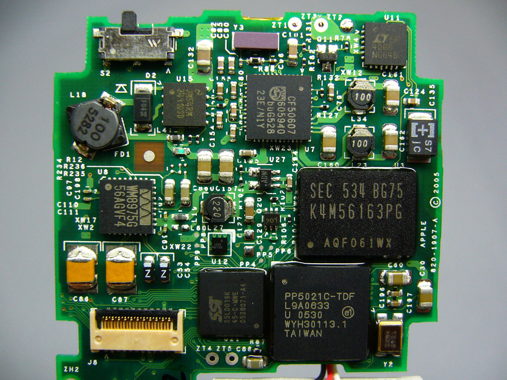
I can tell you what to do from the board picture I see and then you need to improvise to get the job done or just wait few days when I got mine and then I will provide tutorials with pics !
tongue.gif


I do both a bit latter!
cool.gif
 
Nov 29, 2007 at 9:03 PM Post #20 of 3,220
VVs, that sounds fine. I have a 1st gen nano, and if you look at the link of the nano he posted, tell me from that board...the rest i can figure out(like the circuit with caps and resistors, and soldering to the phones port,ect)
 
Nov 29, 2007 at 10:12 PM Post #21 of 3,220
[Locate the WM8975 CODEC to the middle left above the two yellow components.] You can either take the audio feed from either the top (north) of C86 and C87 there, or above the C53 and C54, the two black elements with the Z printed on them. The sound is exactly the same from either one, but the C53 and C54 pair can be inverted to feed a speaker (invert the C54 line). Feeding them straight to your DC blocking caps to your stereo jack would be the same setup for both pairs. Send the signals to the positive lead of a 1uF cap and straight to the headphone jack. Now the datasheet says to put 100ohm resisters after the DC blocking caps to protect from improper usage, but I didn't want to degrade the sound with noisy resistors since I won't be letting anyone use my iPod anyways (who would want to with the way it looks?).

Starting from C86, that's pin 12. Going counter-clockwise, 12 is LOUT1, 13 is ROUT1, 14 is HPGND, 15 is ROUT2, 16 is LOUT2. All this can be gathered from the datasheet, and page 37 will carry the bulk of the information. All the grounds on the WM8975 will have the same voltage, so you can use any ground associated with the chip. I tried soldering my ground wire to the same ground supply as the chip on the LCD side of the 4G iPod board. I soldered it to a tiny SMD capacitor, so it kept falling off. I compromised with a poke-and-listen approach that encouraged me to disable the clicking sound feature. A fun consequence of using external-to-the-iPod-casing caps is that you can still use your LODs. I won't imagine you will, but if you want to use a Bose Sound Dock, the option is there.

nano21.jpg
 
Nov 29, 2007 at 10:29 PM Post #22 of 3,220
Like this? Seems too easy?!? I really appreciate your help on this!


Nov 29, 2007 at 10:37 PM Post #24 of 3,220
Cool, so can I unsolder the c86,87 caps? Or should I just leave them there?
 
Nov 29, 2007 at 10:49 PM Post #25 of 3,220
There's the thing of paralleling inputs and its effects on your lineout's sound. I'm not sure how that would affect it, so you'd have to get some knowledgeable person to answer that. Personally I'd keep it in case, like I said, you want to use the dock's lineout or the headphone out.
 
Nov 29, 2007 at 10:51 PM Post #26 of 3,220
Cool, this should be pretty sweet. You. Are. Amazing.!! Thanks
 
Nov 29, 2007 at 10:55 PM Post #27 of 3,220
Nevermind, I figured it out...thanks again!
 
Nov 30, 2007 at 1:30 AM Post #29 of 3,220
Sure, if all is sucessfull I will post a tutorial!
 

Users who are viewing this thread

Back
Top