The Apple diyMod: My Take on the Famous iMod [56k killer] Featuring 3G, 4G, 5G and nano 1G!
Feb 10, 2011 at 7:02 AM Post #2,357 of 3,220
Well I decided to pop it on the microphone-in pins 5&6 and I also severed the board connection and bent them up to make soldering easier.
Could have done it to the 14 & 17 pins but was curious as to what they are actually connected to...
Could have done it to plenty of others but... hey, whatever.
I did run a ground wire from the chip but after listening (loose wires before I connected them) I couldn't tell any difference from using pins 1&2.... so I unsoldered it.
Still showing on the photo's however....
 
So I Dremel the chassis slightly and bend them around the board right at the DAC, Blob some hot glue into the hole to make sure nothing moved whilst I was testing.
 
The pin photo is poor (phone picture, sorry) but you can see the connections. You can also see the residual solder & hot glue coating from my connection to pins 14 & 17. After this photo I smeared the whole dock with a thin coat of hot glue
Also popped a 120GB HD in there as well while I was at it
wink.gif

 
Sounds certainly as good as the basic mod... has it improved it? Good question, need more listening....


Feb 10, 2011 at 7:10 AM Post #2,358 of 3,220
i_djoel2000
Sorry mate, missed your post.
 
Well it sounds like processing noises, that's what I meant by the OS, but the fact that it only occurs on Rockbox makes we wonder even more 
blink.gif

 
Show us exactly  where the wires run buddy
 
Feb 11, 2011 at 12:17 PM Post #2,359 of 3,220


Quote:
i_djoel2000
Sorry mate, missed your post.
 
Well it sounds like processing noises, that's what I meant by the OS, but the fact that it only occurs on Rockbox makes we wonder even more 
blink.gif

 
Show us exactly  where the wires run buddy


sorry, i was wrong..the buzzing sound still occurs when i run the original firmware as well..
 
what do you think the problem is?
 
Feb 18, 2011 at 10:19 PM Post #2,360 of 3,220
Damn it... i dropped my old DIYMod ipod when I was biking home in traffic, and now I'm pretty sure the logic board is busted: It won't recognize ANY hard drive i throw in it, but luckily the 240GB drive that was in it works in one of my other 5.5g ipods I had laying about. I think it's time to dab at DIYModding it myself. 
 
Does anyone have any idea about where to hook up a ground wire inside the 5.5g ipod? I've looked through about 150 pages, and found one reference to a pad that sits under the clickwheel a little, straight off the DAC. I want to run a cable out the top/side of the ipod (drill a hole, obviously), and hook it up to an amp through that (with 2x 6.3v 220uF Blackgates externally before the 1/8" plug). Ideally someone with experience or photos of doing it themselves would rule, I've only seen the end result, not the insides. I don't really want to take the ground from the LOD pins, since I have no idea which ones inside the logic board they are, and don't have a multimeter on hand to test it out. Any help would be appreciated. 


Feb 20, 2011 at 10:32 AM Post #2,361 of 3,220


Quote:
The voltage rating of the capacitor shows the nominal maximum value of DC voltage it can handle. Since we're working with a max 1.5V, you should get something with a rating a bit higher than that. 6.3V is the normal expected rating for this application.
 
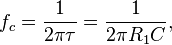
The capacitance you need for the diyMod refers to the high pass filter that forms when you connect your diyMod to your amplifier. When you connect a series capacitor to a parallel resistor to ground (in the amplifier, this resistor is the volume potentiometer), it forms a first order high pass filter, which allows passes mostly high frequencies while attenuating low frequencies from the signal. DC power is, all in all, 0 Hz, a low frequency. Capacitance is the amount of charge that the capacitor can hold, and in our use, you only need a small amount of capacitance in the diyMod. The equation governing the size of capacitor in a high pass filter characteristic is
 
C = 2*pi/(f*R)
 
where C is the capacitance in uF
f is the frequency in Hz
and R is the input impedance of the amplifier.
 
Basically, we want to filer out the DC while passing as much of the audio signal as necessary. Since humans can typically only hear between 20Hz and 20kHz, the highest frequency you want to pass through is 20Hz, which we'll plug into the equation. R is the input resistance of your amplifier, typically 10kOhms up to 50kOhms or 100kOhms. That means that for an amp with 10K input resistance, you need at least 31uF, and for an amp with 100K input resistance, you can get away with around 3.1uF. What amp are you planning on using with your diyMod? Normally, the commercial amps list the input resistance on their tech spec sheets. If it's DIY, it's normally the resistance of the potentiometer.

How did you get that?  Isn't equation for high-pass filter this? :
 
79e190943633c91aa660a4a9351087ab.png

 
where f is cutoff frequency(meaning that the lower bound cutoff frequency point, since you are letting in high frequencies), and you are passing everything over 20Hz(cutoff frequency).  By doing that you are filtering out DC(which has no frequency, f=0, since its not changing being constant), which is less than 20Hz, everything under 20Hz will not pass.
 
Therefore,  you would get:
 
C=1/(2*pi*R*f)
 
Assuming I will use worst case scenario of internal impedance being R=10k ohm,
 
I get C=0.7957uF
 
Conclusion:  No gigantic caps required.
 
I feel like I'm back at Engineering school :)
 
Feb 20, 2011 at 11:27 AM Post #2,362 of 3,220
You're right, High_Q. I've written the equation so many times in this thread that it's made me loopy, apparently. My apologies to anyone who's followed my poor advice.
 
Halfie:
 
Look here. Alternatively, you can solder the wire to the one on the headphone jack. You really should pick up a DMM if you're going to be working on electronics though. They're only $10 at the local hardware store, $20 max for a sufficient model. It'd save you a lot of trouble in the future. I'm assuming you can afford it since you have at least two iPod 5Gs and a 240GB hard drive. A small investment like this will go a long way.
 
Feb 22, 2011 at 4:46 PM Post #2,364 of 3,220
Just to be sue I don't screw anything up...
 
I have the 4G iPod Color.
If I desolder C84 + C86 and re-route them to a pair of capacitors and back up to L2 + L3, then I have performed the iMod?
 
I dont seem to follow any of the guides I see here, its very confusing with SO many different iPods in play on same page...
 
Also, that iMod will give me:
Non-amplified line-out to feed an amplifier from headphone out, correct?
Normal functionality trough dock connector, data, charge, sound out if docked in a dock, correct?
 
 
If I cant find any 47uf 6.3v Black Gate capacitors, what else can you recommend that are easier to find?
 
 
Feb 22, 2011 at 5:17 PM Post #2,365 of 3,220
Im looking into alternative capacitors, I found these:
 
 
[size=x-small]Nichicon MUSE KZ 47uf 50V[/size]
 
 
[size=x-small]Nichicon MUSE FG 47uf 50V[/size]
 
 
[size=x-small]BLACK GATE NX  22uf 6.3V[/size]


[size=small]Elna Silmic II [/size][size=small]47uF 25v [/size]
 
 
...wich sound best and gives best results??
 
Feb 23, 2011 at 10:51 AM Post #2,366 of 3,220
Please don't desolder C84/C86/L2/L3. Please.
 
Besides, if you're talking about those components, then you're not doing the iPod photo. That's the iPod click wheel. Please look here for further guidance.
 
It seems you lack the understanding of the basic premise of the iMod/diyMod. You replace the series capacitors of the line level output of the Wolfson CODEC found in the more popular iPods. These types of DACs put DC on the electrical output signal, so you need to block the DC from getting to your headphones or speakers. If more than 20mV reaches your dynamic loudspeakers for enough time, they will be destroyed. One way of blocking that DC is by putting a capacitor in series with the signal, or putting it through a high pass filter. The high frequencies are passed through, but the low frequencies (DC is basically a 0 Hz signal) are attenuated. We want a high pass filter that only attenuates subsonic signals (so one can hear all the music), so we set a corner frequency, aka -3dB frequency, to somewhere below 20 Hz.
 
The iMod/diyMod converts that high pass filter into a higher quality, audiophile-grade filter by replacing the stock capacitors with higher quality ones. Since the signal passes through the capacitor entirely, it can't degrade the signal by much. The iMod turns your headphone jack into a line out, but that's undesirable because you can no longer use your headphone. People have put up with this before, but I think it's silly. The diyMod shows you how to make whatever set up you want, including replicating the iMod. Preferably, you'd convert your dock line out to a diyModded signal, with or without the capacitors already in series. You can put the capacitors into the iPod, such as in the 4G click wheel and 4G photo, or you can put them in a capped line out dock. Since you have the room, you can put the capacitors inside the diyMod. You can make the line out dock the diyModded source, or you can do what the iMod does and convert your headphone jack into the aforementioned source. Your described scenario converts the line out dock into the diyMod signal.
 
I won't comment on the capacitor quality. If it fits, it'll do.
 
Feb 23, 2011 at 12:38 PM Post #2,367 of 3,220
Quote:
Originally Posted by AT0MAC /img/forum/go_quote.gif
 
If I cant find any 47uf 6.3v Black Gate capacitors, what else can you recommend that are easier to find?


Does anyone have an alternative to these caps? Partsconnexion The sites listed in the guide don't have the part anymore, and although people mention that it's a matter of personal taste on what capacitor to use, I'd prefer to use something that's fairly common/standard since I'm fairly new to the audiophile business...

 
Quote:
joneeboi said:
/img/forum/go_quote.gif

Please don't desolder C84/C86/L2/L3. Please.

 
You mention not desoldering the caps/inductors, but many of the pictorials show them off. I noticed on the tutorial web site that the instructions for the other models have a warning on top not to do so, but this is missing from the 4G click wheel. Thanks for the verification.
 
Feb 23, 2011 at 2:19 PM Post #2,368 of 3,220


Quote:
Please don't desolder C84/C86/L2/L3. Please.
 
Besides, if you're talking about those components, then you're not doing the iPod photo. That's the iPod click wheel. Please look here for further guidance.
 
It seems you lack the understanding of the basic premise of the iMod/diyMod. You replace the series capacitors of the line level output of the Wolfson CODEC found in the more popular iPods. These types of DACs put DC on the electrical output signal, so you need to block the DC from getting to your headphones or speakers. If more than 20mV reaches your dynamic loudspeakers for enough time, they will be destroyed. One way of blocking that DC is by putting a capacitor in series with the signal, or putting it through a high pass filter. The high frequencies are passed through, but the low frequencies (DC is basically a 0 Hz signal) are attenuated. We want a high pass filter that only attenuates subsonic signals (so one can hear all the music), so we set a corner frequency, aka -3dB frequency, to somewhere below 20 Hz.
 
The iMod/diyMod converts that high pass filter into a higher quality, audiophile-grade filter by replacing the stock capacitors with higher quality ones. Since the signal passes through the capacitor entirely, it can't degrade the signal by much. The iMod turns your headphone jack into a line out, but that's undesirable because you can no longer use your headphone. People have put up with this before, but I think it's silly. The diyMod shows you how to make whatever set up you want, including replicating the iMod. Preferably, you'd convert your dock line out to a diyModded signal, with or without the capacitors already in series. You can put the capacitors into the iPod, such as in the 4G click wheel and 4G photo, or you can put them in a capped line out dock. Since you have the room, you can put the capacitors inside the diyMod. You can make the line out dock the diyModded source, or you can do what the iMod does and convert your headphone jack into the aforementioned source. Your described scenario converts the line out dock into the diyMod signal.


Joneeboi: I see you a quite the ignorante guy... Try help people instead of insulting them!
I do understand the premisses in why people are doing it, my problem is simply that all the guides I see talk about the 4G, 5G, 5.5G or mini in details, but the 4.5G color model is kindly left out.
Even the link you put up, there is one single picture of were to take the lead out of the DAC from, but none info what so ever about what to do after that.
 
What im asking for is a guide to were the signal goes AFTER i tap it from the DAC.
Also, what I hope to achieve is one of two things:
 
option a) Doing the iMod, using a headphone amp and listen to lovely music but maintain full dock abilities.
or
option b) Doing what-ever-mod and using the build in volume attenuator to drive the headphones right of the output, without any headamp, with full dock abilities intact and with improved sound quality.
 
 
If it makes you in a better mood, im not electronics [size=x-small]engenieur or anything related, but i am audiophile to the bone and thats why im trying to improve the sound off my iPod to have a portable FLAC player.[/size]
 So pardon me If my questions seem stupid to you, but if I know my fellow audiophiles right there are many more like me out there who would appreciate a little help in matters like this.
Thank you.
 
Feb 23, 2011 at 3:38 PM Post #2,369 of 3,220
AT0MAC:
 
I don't think Joneeboi was trying to insult you. If you're referencing "It seems you lack the understanding of the basic premise..." you shouldn't take that as an insult. He's been more than helpful to all who've asked questions in the thread.
 
For more pictures, check out the gallery: https://picasaweb.google.com/joneeboi/4GPhoto#
No words, but I think you can figure out what to do, if not, then ask~
 
Someone please correct me if I'm wrong, but I'll do my best.
a) If you're doing an iMod, that means that from the DAC, you'd be wiring to your capacitors, then to the headphone jack (DAC > caps > headphone jack). I've not seen any pics of this (probably one of the earlier pics in the thread where the bandwidth was exceeded).
b) If you're doing a version of a DIYmod where you want to keep the headphone jack stock, then you'd wire DAC > caps > inductors (check pics for exact ones). However, this would only give you the improved SQ from the dock port. The SQ from the headphone jack would still be stock.
 
As far as I know, the only purpose of this mod is to have a high quality line out that would have to be combined with an external amp. The whole point is to bypass the iPod's internal amp/volume attenuator which is lower quality.
 

Users who are viewing this thread

Back
Top