Sangaku DIY NuTube Headphone Amp / Preamp
May 25, 2022 at 2:21 AM Post #91 of 144
Out of interest, which Sparkos are you using? The SS3601?
I used the SS2590 (Pro) in mine more to get a closer match to the BOMs OPA551 max output current of >200mA (to drive power-hungry headphones), but noticed while researching that the SS3601 doesn't specifically state that it is unity-gain stable whereas the SS2590 is marked as unity stable in the spec sheets. I'm a novice at such troubleshooting but I wonder if unity instability could cause the DC offset you are seeing.

I'll need to go check output offsets on my 2 Sangaku units to compare.
Instability can cause oscillation, not offset. It seems likely the low input current value of the BOM op amps is significantly different enough from Sparkos (in my case, the S3601) that it causes this issue. But idk for sure
 
Last edited:
May 30, 2022 at 12:17 AM Post #94 of 144
Here's my take on the DIY Sangaku - the SonnyGaku. Re-designed 6-layer PCB that makes a bunch of changes:
  1. Removes all of the PSU stuff other than the filter caps
  2. A lot of SMD components to save space in some places - Sumusu resistors throughout except for the 1 ohm output resistors
  3. Replaced the DN2535N3 with CPC3703CT
  4. Vishay z-foil trimpots
  5. Nutubes are mounted on daughter boards with rubber standoffs, connected to main board with soft wire
  6. All PCBs in the amp chassis are mounted with rubber standoffs
  7. All jacks, switches, etc., use 2.54mm spacing connectors so anything can be used.
  8. Film cathode caps and filament caps - no ceramic at all (other than for the relays)
  9. Extra space for coupling caps - have tried Miflex and Mundorf so far.
  10. JFET buffers before and after the Nutubes for better compatibility with volume control methods
  11. XLR pre out with toggle on/off
  12. Remote control 256-step ladder attenuator
  13. PSU section has separate supplies for: +/-18V (AMB Sigma 22), 70V (B+ from Neurochrome Maida), 12V (relays, etc), 5V (digital stuff), and 0.7V (using an LT3045)
  14. Custom PSU interface board with relay trigger and the rectifier/cap combo for the Maida.
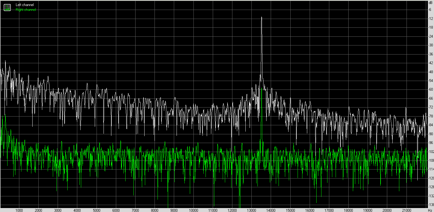
The SonnyGaku provides a significant noise floor reduction. The normal DIY version and even the retail version have Nutube hiss with more sensitive headphones, like my Borealis. SonnyGaku is nearly silent. With Sennheiser 6x0s, it is silent. The noise from the pre-out is all but eliminated as well. Also compared to the normal DIY version, much tighter bass (though I achieved better bass just with upgraded coupling caps in a DIY version). The Sparkos opamps are a nice improvement over the OPA551. I had considered the larger Sparkos, but don't really need the extra power.
Do you remember and do you mind sharing which upgraded coupling caps you used to improve the bass?
 
May 30, 2022 at 12:24 AM Post #95 of 144
Do you remember and do you mind sharing which upgraded coupling caps you used to improve the bass?

I have tried both the Miflex KPCU-03 and the Mundorf MCap SUPREME EVO SilverGold, and I'd be hard pressed to tell a difference between those two in this application. In the normal DIY version, Auricap XO are small and easily fit, also lead to improvements.
 
May 30, 2022 at 1:47 AM Post #96 of 144
To those of you using the smaller Sparkos: you have to reduce all the resistors after the JFETs by a factor of 10. Then change the 100 ohm resistors on the JFETs to about 20 ohms. This will get DC offset below 10mV and not cause clipping.

Hi SonnyMarrow, Great find!. Does this look right for the resistor locations after the JFETs and their new values based on your recommendations?

Screen Shot 2022-05-29 at 10.44.24 PM.png
 
May 30, 2022 at 1:57 AM Post #97 of 144
Hi SonnyMarrow, Great find!. Does this look right for the resistor locations after the JFETs and their new values based on your recommendations?

Screen Shot 2022-05-29 at 10.44.24 PM.png

Apologies, I was a little unclear. You only have to change the resistors from jfet to opamps. So R25, R26, R28, R29, R18, R19, R22, and R23. Reduce these by 10x as you have listed. The four jfet resistors, 20 ohm seems to be the sweet spot. Technically, going into a 300ohm load, you can’t have the amp all the way up, but that would be insanity anyway. And if you drop them to 10ohm for more power output, you’ll overheat the jfets. 20 ohm is a good compromise as you’ll likely never hit a scenario where you’re maxing the amp. There’s also high gain if more volume is needed. The sparkos are only like 15mA class A anyway lol. Oh, you’ll also want to have the trimpots set to their lowest possible resistance values while still balancing the channels.

Mitch in this thread actually discovered the dc offset issue and then it was a collaborative effort on discord by people smarter than me. This solution isn’t perfect, but it’s worth it IMO to use the sparkos over the opa551.
 
May 30, 2022 at 2:09 AM Post #98 of 144
I have tried both the Miflex KPCU-03 and the Mundorf MCap SUPREME EVO SilverGold, and I'd be hard pressed to tell a difference between those two in this application. In the normal DIY version, Auricap XO are small and easily fit, also lead to improvements.
Thank you. Any other "easy" improvements on the normal DIY version? I am starting to put my Mouser BOM together.
 
May 30, 2022 at 2:33 AM Post #99 of 144
Thank you. Any other "easy" improvements on the normal DIY version? I am starting to put my Mouser BOM together.
You could use non-magnetic resistors. Vishay / Dale RN series or Takman metal film are popular on a few builds (including mine) on this thread. You can also use a TDK volume pot. The transformers were the hardest component to find when I was building mine, but I think Mouser/Digikey just got a restock.
 
Jun 24, 2022 at 2:52 PM Post #102 of 144
Hey anyone know the screws that mount the case to the pcb?
There are no screws that mount the PCB to the case directly(the PCB slides into the grooves of the inside of the case. Instead, the PCB is screwed into the face and rear plates via the power supply, RCA, XRL, and headphone jack. Then the faceplates screw into the main chassis(4 corners) and the PCB is held in place from either side and the grooves it’s sitting in.
 

Users who are viewing this thread

Back
Top