Roll Call: Who's building, built, or thinking of building a beta22?
Oct 30, 2007 at 3:39 AM Post #241 of 3,218
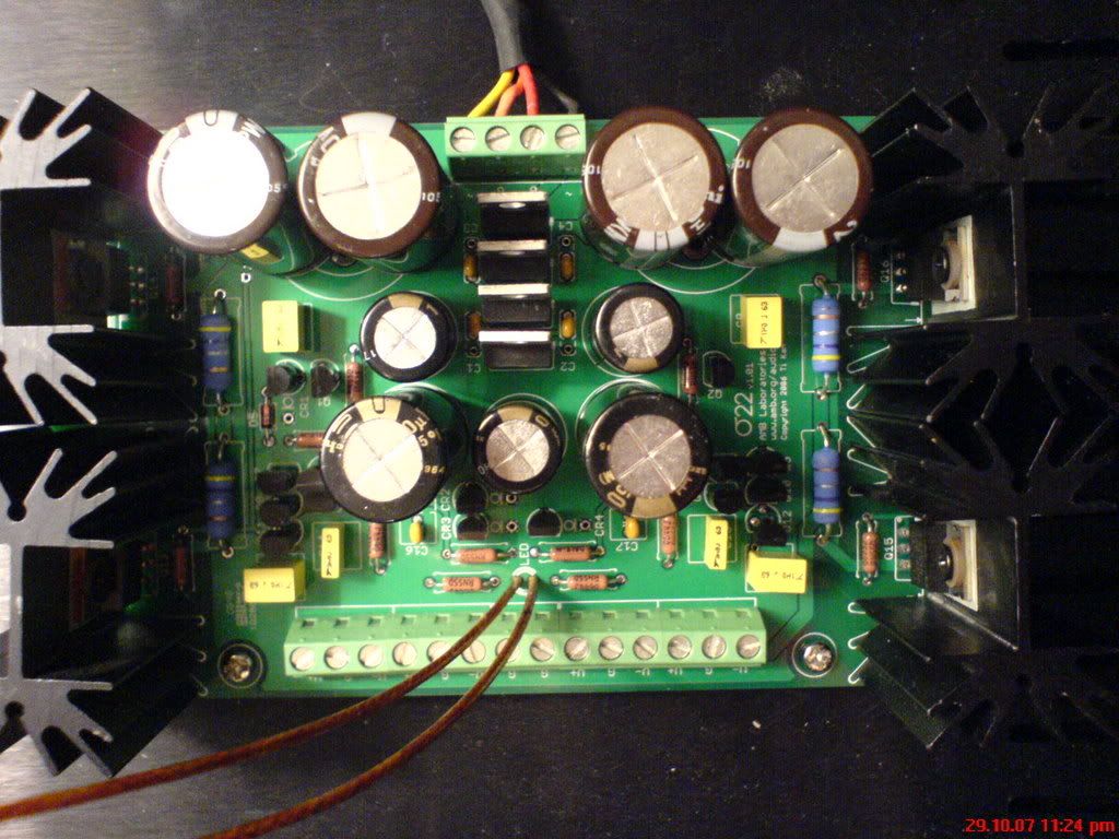
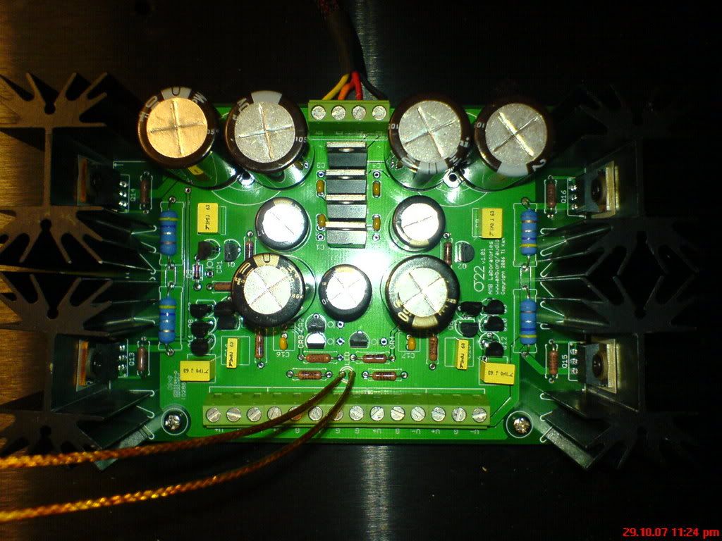
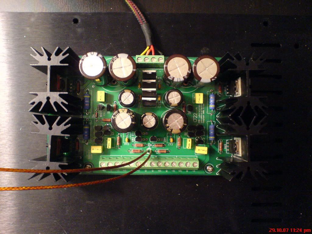
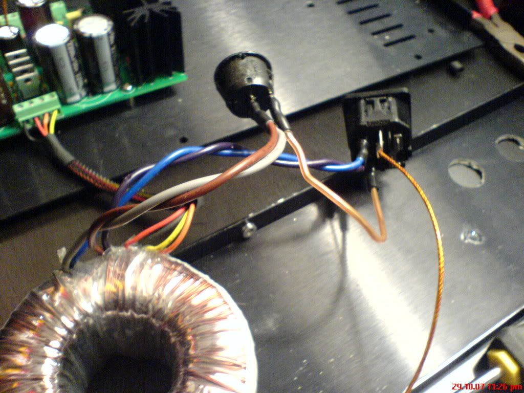
k more follow up bad news from me! i just put together a totally new S22 i had that i was planning to use for a separate project down the line and swapped that in to my b22. STILL no signs of life!! no led light, no noise, no warmth, nothing
frown.gif
! ive attached some photos, ive inspected the underside of the board carefully for cold joints and cross bridges, it looks fine. could it be a problem with my IEC entry module or with the fuse or switch im using? the fuse hasnt blown at all in trying to get it going. the switch im using is just a basic 2 pole switch i picked up from a local electronics shop. i know the power cable im using is fine, and i ASSUMe that there wouldnt be anythign wrong wtih my trafo...so...suggestions? ive attached some photos (taken on a cell phone so sorry if the quality isnt up to par). but yea, similar scenario to my problems i was having a few weeks ago, clearly its not due to the reversed rectifiers this time
tongue.gif
! anyways, lemme know guys, obviously any help would be VERY much appreciated!
DSC00050.jpg

DSC00048.jpg

DSC00049.jpg

DSC00051.jpg
 
Oct 30, 2007 at 3:48 AM Post #242 of 3,218
i dont need to tin the wires before screwing them down in terminal blocks do i? it would be nice if its something REALLY obvious like that, but sadly i doubt it
 
Oct 30, 2007 at 5:25 AM Post #243 of 3,218
Quote:

Originally Posted by el_matt0 /img/forum/go_quote.gif
i dont need to tin the wires before screwing them down in terminal blocks do i? it would be nice if its something REALLY obvious like that, but sadly i doubt it


No, that shouldn't be necessary.

Looks like you are using an IEC with an integral fuse holder. you do have a fuse installed in there, right?

With your DMM in AC Volts mode, measure across ~ and G, and then the other ~ and G. What do you read? Switch the probes to across the two ~ terminals. What do you get now?
 
Oct 30, 2007 at 5:34 AM Post #244 of 3,218
yea i do have a fuse in there. while the secondaries are screwed into the terminal blocks, measuring across the pads you suggested all read 0 VAC. even with them unscrewed, measuring across black-red for example with the power on and plugged in there is still 0 reading. clearly it looks to be something with the IEC wiring or my fuse or switch...but im a little perplexed as to which to be honest!
 
Oct 30, 2007 at 5:40 AM Post #245 of 3,218
Remove the fuse and measure with your DMM ohms mode. Should read close to zero ohms. If not, it's blown. Measure the AC voltage across the neutral and hot tabs of the IEC, do you get the full AC mains voltage? Also, what kind of switch is it? I hope it's not momentary contact. Measure the AC voltage across the switch contacts with the switch in the off position. You should also get the full AC mains voltage.
 
Oct 30, 2007 at 3:35 PM Post #246 of 3,218
k, measuring across the fuse itself does show 0 ohms, and i can still see the filament is intact not burnt out. however, i seem unable to register any AC voltage across any of the tabs of the IEC or between the two poles of the switch! my switch isnt momentary i dont believe (those are moreso push button ones etc right). its just a basic 2 pole rocker switch. i guess its starting to seem like it might be a problem with the IEC? i did notice one thing, that when soldering to one of the tabs on the IEC, the hot one i believe, the metal did heat to the point that it moved slightly by melting some of the plastic. i was able to move it back into place by just reheating it, and it was only off by a few MM in the first place, and nothing is visibly melted or damaged now, so i assumed no permanent damage resulted....any more suggestions on how i can narrow this down, or does it look like its the IEC? bummer if it is because im absolutely beat on a good place to order or find one in my general whereabouts!!
 
Oct 30, 2007 at 5:10 PM Post #247 of 3,218
You sure you have the fuse installed correctly? Most IEC's have a spot for a "spare" fuse in addition to the primary fuse. Most of the time they're in the same drawer. Just a thought of something simple that could go wrong and would produce the results that you're seeing (no AC at the IEC). You should be able measure the resistance from the hot (non fused) tab to the tab that you're using (fused) and see 0 ohm there. If you don't then you know something about the fuse setup is hosed.
 
Oct 30, 2007 at 5:26 PM Post #248 of 3,218
nate man i love you!
smily_headphones1.gif
always being able to pinpoint my silly mistakes so darn well! i had NO idea that the top spot in the fuse "drawer" was a spare slot, i thought from that position it would reach the contacts - oh so wrong lol! anyways, fuse in the right spot = life. everything seems fine. now to tweak the other 4 boards so i can hopefully get sound from this beast! thanks as always
 
Oct 30, 2007 at 5:27 PM Post #249 of 3,218
oh one quick question that i was kind of unable to determine from ambs site. if im keeping my trafo and iec in a separate enclosure, but all 5 b22 and s22 boards in the other enclosure, do i still need to use a ground loop breaker for connecting the IEC ground to the chassis? im currently assuming no...
 
Oct 30, 2007 at 5:57 PM Post #250 of 3,218
Quote:

Originally Posted by el_matt0 /img/forum/go_quote.gif
oh one quick question that i was kind of unable to determine from ambs site. if im keeping my trafo and iec in a separate enclosure, but all 5 b22 and s22 boards in the other enclosure, do i still need to use a ground loop breaker for connecting the IEC ground to the chassis? im currently assuming no...


No you don't. Check out the picture marked option 2 under Wiring and Ground on amb's site...it also lets you know which panel components need to be isolated from the chassis.
 
Oct 30, 2007 at 6:51 PM Post #251 of 3,218
yea i was going to ask about that, so im using a 4 pole speakon connector for my umbilical. it has a tiny rubber o-ring, but that doesnt count as being "isolated" does it? whats the proper technique for isolating these larger components, ive never used isolating washers or anythign so im not sure exactly what id need to order. same thing applies for my panel mount XLRs...! is it possible to use teflon tape or something of the like, or is a proper washer the standard?
 
Oct 30, 2007 at 7:20 PM Post #253 of 3,218
Oct 30, 2007 at 7:22 PM Post #254 of 3,218
I'm just about to start building a four board fully balanced beta22. My only dilemma (currently) is finding a nice enclosure which won't cost an arm and a leg to ship to the UK. Best I can come up with locally is a 2U rack box which is a bit too big (wide) for my preferred location. Ideally, I'd like something less than 15.5" wide but I can go to 16.75" at a push. It only needs to take the four boards, pot and connectors. The PSU will be housed separately. Any ideas?
 
Oct 30, 2007 at 7:33 PM Post #255 of 3,218
Im going for the Hifi2000 Slimline cases for my 4-channel build. I think you can fit the 4 boards in a Galaxy case also, the widest being 310mm inside. They are available from www.modushop.biz and www.audiokit.it.
Quote:

Originally Posted by Alick /img/forum/go_quote.gif
I'm just about to start building a four board fully balanced beta22. My only dilemma (currently) is finding a nice enclosure which won't cost an arm and a leg to ship to the UK. Best I can come up with locally is a 2U rack box which is a bit too big (wide) for my preferred location. Ideally, I'd like something less than 15.5" wide but I can go to 16.75" at a push. It only needs to take the four boards, pot and connectors. The PSU will be housed separately. Any ideas?


Users who are viewing this thread

Back
Top