I like the idea of a vinyl tube as coupler but really, if you could find some sorbothane to hollow a path, that would likely be best. It probably has the most similar characteristics to human skin. Maybe something like these used back to back. They're on eBay.
I use the vibro veritas for IEM measurements, instead of the IMM6. not because I find it to be a superior coupler, it's not. the IMM6 actually rolls off later on in the trebles. on the other hand my IMM6 rolls off in the low end(I tried to seal everything, it didn't improve) when the veritas is almost right without any compensation in the low end. overall it would be better to compensate the low end of the IMM6 in my case and use it for measurements. the plug doesn't work in my inputs but I get it to work with small crocodile plugs on the jack ^_^.
why I don't do that? I started with the veritas and have some measurements of IEMs I no longer have with me, so I decided to stick to the vibro veritas for consistency.
now if I was looking for more than very basic FR graphs, I would get an actual microphone I could use with my scarlett2i2. neither the veritas nor the IMM6 work with it and I'm as frustrated of it not working as I am of not understanding why. ^_^ it's too bad because the input could be so much cleaner than the little startech crap I use as input.
so in practice the IMM6 really helped me to set up a pair of speakers(and check if my original pair was ok). having it plugged into my cellphone and moving around in the room, now that's next level practical stuff. I loved it.
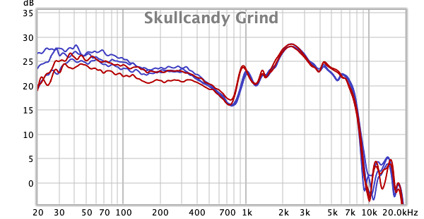
so here is an example of what I get with the vibro veritas and REW, I show er4sr because it should be very close to your er4, and xba-c10 because we have that one in common. and the hf5 because I always felt the C10 was a close enough parent to EQ one into the other(super cheap hf5 without isolation).
this one is real uncalibrated, uncompensated, non smoothed data
this one is the same data compensated to get the er4sr to follow the graph on the certificate that came with it. it actually shows too much trebles based on my hearing for other IEMs, maybe if I spent more time testing for insertion depth I could get that right, but the er4 is a special kid when it comes to going deep and I'm not sure I go deep enough compared to the rest in an actual ear. I also struggle when it comes to comparing vented and sealed stuff. they don't measure the same variations I feel in my ears(often hearing way more low end than what I measure).
and this is still the same data, but compensated to better resemble online stuff in general. to my ear at least, the xba-c10 really drops like a stone after 10khz, and that compensation seems to best represent how I feel(still raw though).
in the end what matters are the variations between 2 measurements and I don't bother with compensation when I'm testing stuff for myself(tips, filters, EQ, source impedance variations...) but when I show stuff online I usually try to have a general look similar to online stuff so that people who don't know how to properly read graphs end up being only slightly wrong ^_^. I could warn about not making comparisons from graph of 2 different provenances 10 times a day, and still have people who will do it because it's simple.
I’ve been away for a while, but thank you for sharing that. It’s good to know how others are making measurements.
About the Focusrite Scarlett: It has 48V phantom power, no? You might fry the iMM-6 if you managed to wire it up to that. The capsule should be similar to the old discontinued Panasonic WM-61A electret condenser, which had a standard operation voltage of 2V. (Maximum is 10V according to its datasheet.)
The 1/8” TRS jack for computer mics typically supply 5V:
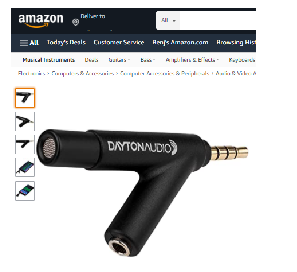
The one in the Startech works fine with the iMM-6 using a headset to PC adapter like this one:
https://www.amazon.com/gp/product/B008OB2NHA/ref=oh_aui_detailpage_o01_s00?ie=UTF8&psc=1
The Startech isn’t bad at all and I’m getting reasonably good results with it. If you’re determined enough, I suppose you could buy an adapter to downconvert the Scarlett’s 48V phantom power to 5V. But those adapters can be expensive unless you build it yourself. You could buy a UMM-6 or an EMM-6 for the price. Here’s Sennheiser take on it: link.
BTW, here’s a modest proposal: we should start a new thread called "The Measurement Gallery” or something like that. Anybody can post measurements as long as it is clear how they were made. With that in place, I don’t think the data will be too misleading. Even if the individual results are inaccurate, a reader might see a pattern emerge if enough measurements are posted. It would start small, but maybe it could eventually turn into a useful resource worthy of a sticky.
The thread’s first post would serve as an index, with links to the things being measured. I’d start the thread myself, but someone who is here more often than me should make the first post.
@goodvibes
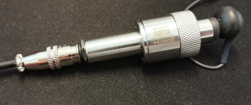
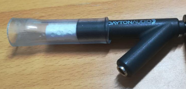
Thank you for the idea. I might try that later, when it’s convenient. The vinyl tubing was just lying around here and is cheap, so I started with it. I have access to softer vinyl as well as silicone tubing, which might be a little closer to the acoustic Z of human skin. Moreover, their inside diameter is 7 mm–closer to average than the ¼” ID that I started with. Let’s see which makes a bigger difference—the small change in diameter or the change in tubing material.
Experimenting with tubing material to get it closer to the acoustic properties of human flesh is good, but at the same time it’s getting farther away from the materials used in an IEC 711 ear simulator. We’ll see what happens.
I was thinking of adding features to my Dayton iMM-6-based rig a little bit at a time. Maybe a mold of my outer ear first, then a simulated head around it much, much later.
The premise here is that if headphone and speaker measurements at the ear’s opening are the same (even if blocked), then the response at the eardrum should be the same also. That’s a big if, and there are some folks who dispute the claim. But there are others who have reported good results with it. For example, look no further than the Smyth Realiser system’s in-ear microphones.
Keeping in mind the title of this thread, it should be possible to build your own binaural mic system for far less than $170, using WM-61A clones and a little elbow grease.
If you needed more motivation to do this, consider, also, the claim being made by David Griesinger here:
https://youtu.be/a-JGAobDwGs?t=660 Please fast forward to 11:00 to see (and hear) several subjects' in-ear measurements of pink noise being played by an HD600.
If you believe this video, then we can potentially get much better DSP corrections to a headphone’s response if the corrections were based on measurements made with mics inside our own ears, instead of a dummy head’s. DG advocates making measurements near the eardrum using a microphone similar to the Etymotic ER-7C Clinical Probe Microphone System.
On his web site, he has a tutorial video on how to construct comfortable low-cost probe mics that can measure near the eardrum. It’s a private YouTube video, but the link can be found on his site.
At the end of that tube is a modified Audio Technica ATR3350iS lavalier mic. I have a feeling that you can build a removable attachment for the iMM-6 instead of doing an irreversible mod on the AT. That could be a future project.
I had thought about using the binaural mics, but I've never come across a set with calibration files. Does anyone know if they make such a thing? Though I figure calibration files don't matter too much if all you want to do is compare headphones. Binaural mics might be interesting to collect headphone sound profiles and swap between them with a reference headphone.
I was discussing turning the phantom 48V into 2 (or 5v apparently) in PM with someone not long ago, my personal investigation in the matter concludes that I'm a scared kitten who doesn't try anything if it could destroy a device after a mistake.
I have a vague general idea, I have resistors and stuff, just not any guts.
about measuring headphones for personal purposes I would definitely go with the mics in the ear canal. it's not perfect and the mic isn't placed at the eardrum so some changes would be needed, but I assume that a little trial and error would do just fine in the end to figure out the correct compensation. the thing is, all this measurement fun I've thrown myself into is focused and limited to IEMs. so getting the coupler in the ear canal and an IEM at the same time, that seems tricky ^_^. but if I was mad about fullsize headphones, I would definitely go for some couplers in the ear and EQ the hell out of my the headphones.
I have those binaural mics and can attest they work well for what prescient suggested: comparing two sets of transducers. For absolute measurement they are of course totally unacceptable because they come with no calibration file. The production variance is such that my L mic is about 2dB hotter than the R. But for turning one set of cans into another they work great; I'm about to post my procedure for comparing my PM-3s to my HD800 using measurements/filters done with these. I have not seen any binaural mics that come with calibration.
As far as having mics at the meatus vs. at the eardrum: I have seen literature suggesting that the effect of the ear canal is not strongly affected by direction (see here, p. 42), and thus we might expect whatever effect it has to stay consistent between headphones. Something more recent might disagree; I don't recall seeing anything to the contrary in Xie's book, though. Since I managed to perforate my eardrum as a young lad, I'm a bit loathe to use probe mics anyway.
@prescient
I suppose if you already had a calibrated mic, you could calibrate an unknown mic using it. Depending on the application, the second-generation result might be good enough. It’s interesting, what you suggest: use DSP to undo one headphone’s impulse response and replace it with another’s. It’s essentially a subset of what the Smyth Realiser does, but done on the cheap. I’d love to see (and hear) the results.
@castleofargh
If you’re afraid of the 48V phantom power frying the mic, maybe you can use batteries, so that the voltage going into the iMM-6 never exceeds the battery voltage. It’s not hard. Here, I cobbled together the following embarrassing setup within a couple of minutes after making the sketch:
Oh well, I don't have all my tools this weekend. It would have been easier if I had that headset to PC adapter that I was talking about earlier. Without it, it was difficult to connect the alligator clips without shorting. I was able to get the following measurement in REW from that setup going into an old Focusrite Saffire 6:
I’ll have to measure that again because I jammed the IEM’s stem way past the foam tip.
About the probe mic—yes, I would imagine that getting it and an IEM positioned properly would be tricky. But that hasn’t stopped this guy Sonove from doing it. Lol, seems legit:
What’s also interesting is that he compares measurements done with the ER-7C probe mic, binaural mics, and his DIY coupler.
@RRod
That’s terrific! I’d love to see your procedure. I’m on the fence right now if I should just pull the trigger and order the mics and the battery module and be done with it. The price just went down to $150, but I know it can be made for a lot cheaper.
BTW, directionality isn’t necessarily the objection. If the transducers’ measurements at the (blocked) meatus is the same, does it always mean that the (unblocked) response at the eardrum will be the same also—especially if one of the transducers is a loudspeaker?
Also, in the video linked in my post above, DG says that he tried a different method and got results almost as good as putting probe mics in his subjects’ ears. Essentially, he had them match the perceived volume of 1/3-octave band-limited noise to the band around 1 kHz or 500 Hz. It’s pretty much the same thing we’ve been doing here for years in the how-to-eq threads. Apparently these techniques are described in ISO and DIN standards that go back even earlier.
He tells the audience that he has developed a Windows application that does this and that he’d send them a copy of the program if they’re interested. Hmmm.
@RRod
That’s terrific! I’d love to see your procedure. I’m on the fence right now if I should just pull the trigger and order the mics and the battery module and be done with it. The price just went down to $150, but I know it can be made for a lot cheaper.
BTW, directionality isn’t necessarily the objection. If the transducers’ measurements at the (blocked) meatus is the same, does it always mean that the (unblocked) response at the eardrum will be the same also—especially if one of the transducers is a loudspeaker?
The procedure is roughly:
.Make repeated impulse measurements to account for mic & headphone position variability
.Choose some mean/median measurement
.Trim/window that measurement to make a filter
.Make the inverse filter (I use the Audacity version of this.)
Then I can apply filters and inverses to tracks as I need to do the comparison, with loudness matching as a final step. This lets me feed the two versions of the track into an A/B comparator and let me switch seamlessly between both "headphones".
Re where to measure:
If the variations in response due to the interaction of the pinnae with speaker angle do not change the effect of the ear canal, then I think it's reasonable to assume that putting different speakers at the same angle shouldn't change things either. I haven't been able to find anything that says that for relative measurements a differing effect of the canal needs to be assumed.
this really challenge my recent picture to test impedance.
I found my bread board under a box like 2 hours after I had finished my measurements
.
in fact I did try linking my laptop and the focusrite into the coupler, but all it did was measure the massive noise of my laptop more accurately ^_^. I didn't mention it because to me that was a failure, but a battery, now we're in business. I'm going to try with USB and if it's too noisy, I'll "invest" in batteries.
I'm in the middle of a few other stuff I need to finish first, setting up my amp to output a given voltage with minimum channel imbalance is hard and boring so when it's done I finish what I was doing before I start changing again to adjust the loudness for IEMs. + my liver is learning how to swim in alcool like every Xmas, so everything goes slowly. but it seems really cool and I'd love to have better distortion/noise values if the coupler allows it.
side question for whoever knows. what is the purpose of showing phase with the FR measurement in REW? it's always a total mess, usually even after using the "estimate IR delay". I get the proper stuff when measuring impedance, but never with FR so what's the point?
side question for whoever knows. what is the purpose of showing phase with the FR measurement in REW? it's always a total mess, usually even after using the "estimate IR delay". I get the proper stuff when measuring impedance, but never with FR so what's the point?
I assume you're already checking the box to unwrap the phase, after which it can still look like a mess. The point is a) to show the whole picture of the impulse and b) to remind you it exists, so you remember to look at the excess group delay to see where your response might reasonably be considered minimum phase.
yeah I should have mentioned the unwrap when needed, but that's not what I was talking about. I'm guessing the differences could be a mix of the coupler itself and a little time delay in the loop even if there is an option to use the second channel as time reference, but it doesn't get me close to the actual phase.
oh well, I don't really care, I just thought maybe there is something I'm doing wrong or maybe there is some clever purpose that eluded me like 90% of that amazing little software. ^_^
I have never been able, in my own stuff, to come up with a reliable way to generate a good unwrapped phase or phase delay plot. Some IRs will work fine and others, which shouldn't be too much different, will be all over the place. Group delay seems to work better for plotting. I have read various pages as to why this is, and there are corrections but they involve more programming than "unwrap()", so I've been lazy in trying them out.
well the method they suggest to measure impedance in REW's documentation http://www.roomeqwizard.com/help/help_en-GB/html/impedancemeasurement.html gives a very nice phase response as a bonus. and as all the websites show phase and impedance together, I'm guessing it's the proper way. that's why I'm puzzled with the phase response given with FR measurement. I get that it can have a use, even more so as it's supposed to be used in a room on speakers. but how to use the phase that comes with the FR? IDK
here is my pair of SE215, the almost flat is what I get while measuring impedance. the blue one came with the frequency response(once applied the "estimate delay" thing, not the unwrap). it's probably trying to tell me something but what? that I'm too much of a noob to measure 2 stuff at the same sample rate. ok ^_^. what else?
Perhaps there are some "niceties" in mag/phase for impedance that you don't get for IRs :shrug.jpg:. That phase plot for the IR looks perfectly reasonable, though. As far as interpretation, I find phase delay and (excess) group delay easier to think about than phase angles. Phase delay is especially easy: how many seconds is that cosine component delayed?
don't you dare talk with words as if I understand them!
here, it will probably be more effective than getting me to read the wrong stuff and then wonder why it doesn't make sense ^_^:
https://www.dropbox.com/s/g24xlco9up2i7j3/se215osef.mdat?dl=1
@castleofargh
If you’re afraid of the 48V phantom power frying the mic, maybe you can use batteries, so that the voltage going into the iMM-6 never exceeds the battery voltage. It’s not hard. Here, I cobbled together the following embarrassing setup within a couple of minutes after making the sketch:
Oh well, I don't have all my tools this weekend. It would have been easier if I had that headset to PC adapter that I was talking about earlier. Without it, it was difficult to connect the alligator clips without shorting. I was able to get the following measurement in REW from that setup going into an old Focusrite Saffire 6:
I’ll have to measure that again because I jammed the IEM’s stem way past the foam tip.
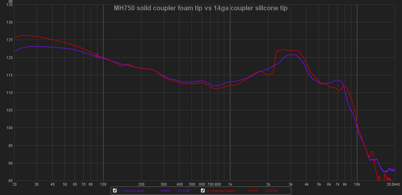
so I finally decided to try (moving up my never ending audio todo list, I do one thing, I have 3new I want to try ^_^).
whatever I tried, it's not worth the effort for FR alone IMO, and even the 30$ startech usb ADC works fine for such purpose into a cheap mic. but the distortion figures went down a good deal using a tablet as DC source (around 2.3v) and measurement done with the focusrite 2i2 as input.
thank you for reminding me to use an external DC supply.
This site uses cookies to help personalise content, tailor your experience and to keep you logged in if you register.
By continuing to use this site, you are consenting to our use of cookies.