Post pics of your builds....
Jul 21, 2009 at 2:01 AM Post #5,416 of 9,811
Well, here is mine...

dsc07271ov7.jpg

dsc07422mq4.jpg

dsc07239rq2.jpg

dsc07301ix0.jpg

dsc07309sd7.jpg

dsc07298mf4.jpg

dsc07289rd3.jpg

dsc07539tu1.jpg

dsc07543ei1.jpg


biggrin.gif
biggrin.gif
biggrin.gif


Cheers
 
Jul 21, 2009 at 9:59 PM Post #5,418 of 9,811
more spdif switch stuff (a work in progress):

3743480917_d54faaf480_o.jpg


3744274932_1a76bddd2b_o.jpg


partial wiring is done; power is there and 3 bits of control (A0,A1,A2) on the switch chip. this allows up to 8 ports of input even though I'm only soldering enough connectors for 4 ports
wink.gif
those are the red molexes on the edge.

the white molex on its own is going to be the single output (at TTL level).

the 5pin molex comes from the cpu (arduino board) and that has the 3 address lines and 2 wires for power.

when you select a remote input, the arduino will program the A0..A2 lines is binary based, so input 1 is 000, input2 is 001, input 3 is 010 and so on. if you build only a 4 port version (like me) you can cut one line out and just use 2 bits.

hopefully I can get the entire thing done soon and then I'll try to write the whole project up.
 
Jul 22, 2009 at 3:49 PM Post #5,419 of 9,811
Quote:

hopefully I can get the entire thing done soon and then I'll try to write the whole project up.


I'd like to see some sort of write up. From thee few skims I've given it it looks like a pretty neat project and something that I could even maybe do. 'Course, I'm not sure exactly what your doing, hence the write up... :-D
 
Jul 22, 2009 at 5:46 PM Post #5,420 of 9,811
I finally finished this one! It was "housed" in a wood base temporarily for the last year...

revMillett Hibrid, here shown with Elna Cerafine's all around and Blackgates as output caps.
IEC, RCA in and Loop out in the back, Jack, Led and Volume in the front.
Steps configured for 25v.

Sounds great and not noise or hum with the 701's
cool.gif
It will replace the PIMETA in the rig as soon as I doublecheck all the biasing!

P1010008.JPG


P1010019.JPG


And here a CKKIII I built for a friend. AMB's standard parts list, with heatsinked output trannies and home made wallwart to keep the trafo away from the amp.

P3180023.JPG
 
Jul 22, 2009 at 6:53 PM Post #5,421 of 9,811
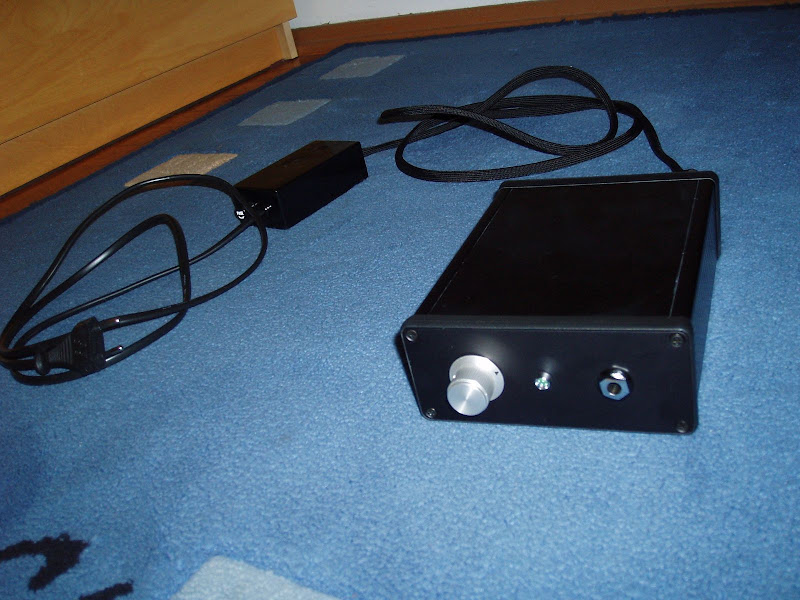
Finally finished casing up my balanced power unit. I built the basic unit over a year ago,
but it was just bolted into the case and the back panel was done. No on/off switch or
indication of power on.
back.jpg


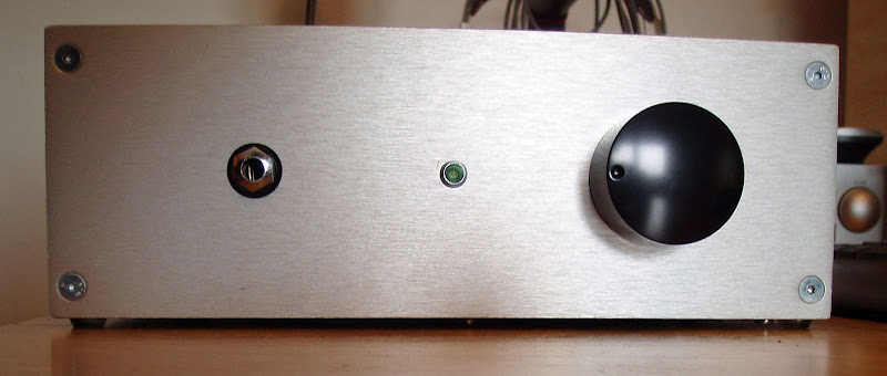
Finally settled on a toggle switch, and added a pair of handles to help shield the bat of
the toggle. Also, I tapped the panel hole for the toggle to avoid having a nut on the front.
The switch is threaded directly into the panel, with a jam nut against the back side.
front_off.jpg


The power indicator is a small right-angle amber unit mounted through the base of the
unit at the back, so it illuminates a soft glow from underneath. I might rip that out and
just put a small amber LED in the faceplate.
front_on.jpg


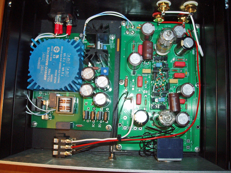
There is a small 12v PSU inside to power a TDR for the amplifier socket, the other two
sockets are fed through noise filters for a transport and dac. The toroid is an 800VA piece,
which is far more current than I need, but it has tighter regulation than a smaller unit.
xformer.jpg
 
Jul 23, 2009 at 10:33 AM Post #5,425 of 9,811
Quote:

Originally Posted by Koyaan I. Sqatsi /img/forum/go_quote.gif
My guess would be Time Delay Relay.

k


Correct, sorry about that.
There is no time domain reflectometer in there.
Quote:

Originally Posted by n_maher /img/forum/go_quote.gif
That's some nice clean work there Mark!


Thanks! Nice to finally finish up some of these stray projects.
 
Jul 23, 2009 at 9:06 PM Post #5,426 of 9,811
a single shot for today:

3749733811_f7b3d759ac_o.jpg


its a realtime clock chip that I will integrate in, well, almost everything. you can see the small watch crystal hanging on its leads. the black cylinder in the middle is a 'supercap', 0.022 farads at 5v. this clock chip (ds1302) has a built in trickle charger to keep this supercap charged, so that you can lose power to the circuit and not lose time/date keeping functions.

as they say, "all products expand in functionality until they have a clock". my spdif switch will soon have a clock feature (for when the switch is not in use, or even on an idle timer).

the ribbon cable goes back to the arduino (or any processor) and you talk to it via a 3 wire SPI-like interface.
 
Jul 24, 2009 at 12:02 AM Post #5,427 of 9,811
Quote:

Originally Posted by linuxworks /img/forum/go_quote.gif
a single shot for today:

its a realtime clock chip that I will integrate in, well, almost everything. you can see the small watch crystal hanging on its leads. the black cylinder in the middle is a 'supercap', 0.022 farads at 5v. this clock chip (ds1302) has a built in trickle charger to keep this supercap charged, so that you can lose power to the circuit and not lose time/date keeping functions.

as they say, "all products expand in functionality until they have a clock". my spdif switch will soon have a clock feature (for when the switch is not in use, or even on an idle timer).

the ribbon cable goes back to the arduino (or any processor) and you talk to it via a 3 wire SPI-like interface.


Seems a bit like feature creep! You can write code that will do it on the uC itself - no need for the external clock. Assuming the Arduino will do a proper, low current sleep that is. Should do?
 
Jul 24, 2009 at 12:29 AM Post #5,429 of 9,811
when you remove power (you've just downloaded new firmware over the FTDI cable) and then you move the device back to its normal location - it loses power. if you have a clock, you do want it to keep going even when power is off.

with a hardware clock, you won't care about software timing and can just 'ask the clock' whenever the polling loop reaches that point again. I can get the mm:ss value and if the old ss is different from the current ss, its time to redraw_clock().

it also knows about 30/31 day month stuff, so it keeps the calendar really simple, in your own code.

for a few dollars (that's all it costs) I think its worth it. my cpu can then use a very cheap ceramic resonator and you just don't care about cpu timing anymore.
 
Jul 24, 2009 at 2:30 AM Post #5,430 of 9,811
I wish I could take pics like linuxworks
redface.gif


Anyway, at last my Bijou is done. Here are some pics to share, hope you like it and thanks for looking!

cheers -zk

Top view, really tried to keep the wires as neat as I could but it's just not my stong suit.
zkinternaltopview1.jpg


Shot of a pair of vu meter buffer/divers from JLM audio
zkinternaltopview2s.jpg


Finished the top lid with plenty of vents, and it also fits nicely! Time to put my tools away and take more pics.
zkbijouglamoursmv3.jpg


Closer look at the top lid, my hymble attempt to mimic that aluminum “brushed” look
zkbijouglamoursmv2.jpg


View from the back, installing the neutriks are so painless, I think I’ll keep using them
zkbijouglamoursmv4.jpg


..and finally enjoying some music. Cheers!
smile.gif

zkbijouglamoursmv0w.jpg


Users who are viewing this thread

Back
Top