Post pics of your builds....
Aug 22, 2009 at 8:30 AM Post #5,596 of 9,811
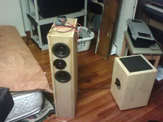
Well I haven't built any headphone gear of late, but I have been using my buffalo/bijou combo as the source/pre for my facewoofer and recently these new speakers.

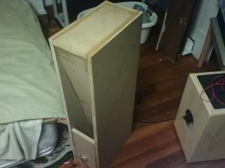
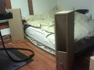
They were built from a PE kit based on the fairly popular Tritrix MTM DIY speaker design. Overall I am very pleased with the sound considering the price (~$220 built). For my tastes, they seem capable of covering the entire range of music. The biggest surprise was the low end output. I expected punchy/tight but rolled off bass b/c of the driver size, but these things sound downright cavernous for 5" drivers. I guess that's the magic of a well designed TL box...

 
Aug 22, 2009 at 10:41 AM Post #5,597 of 9,811
Awesome builds jazzist and chobint!
smily_headphones1.gif
 
Aug 22, 2009 at 10:40 PM Post #5,599 of 9,811
Thanks as well for the comments. Jazzists I agree that the black backplane and green baby-boards looks great. It's too bad that it will probably be encased in steel, because I think that amp would be a great candidate for a clear lexan case.
 
Aug 23, 2009 at 7:20 PM Post #5,602 of 9,811
Not headfi but stage 2 is almost complete. Just a little glitch with the tube stage to work on. The tube stage splits the incoming signal for AB duty in the power stage and amplifies the signal.

Solid state with single ended input sounds great even at +-12v using a single pair of IRF630/IRF9630. The final build will be 2 pairs at +-36v which should give me ~160 watts per channel(I'll need more heatsinking!) Two power supplies, one is all sand and the other has none at all.

TStage.jpg

SSStage.jpg
 
Aug 23, 2009 at 8:57 PM Post #5,604 of 9,811
HI DKJones 96 -

Very interesting...

Nice little heatsinks on the perfboard in the 2nd picture. What are they and where did you get them???

Thanks,
 
Aug 23, 2009 at 11:59 PM Post #5,605 of 9,811
The tubes will run at 90v(0B3) so I don't exceed the heater-cathode voltage rating of the 6SN7s. I was running it at 165v while testing with 12SN7s tho(pictured).

The heat sinks I got out of a junk monitor. Sorry. I've been looking for more since they are perfect for a lot of prototyping stuff being that they are small. I end up taking them off of previous ptypes to make new ones.
 
Aug 24, 2009 at 6:59 PM Post #5,606 of 9,811
Quote:

Originally Posted by DKJones96 /img/forum/go_quote.gif
The heat sinks I got out of a junk monitor.


I'd bet they are made by Fischer. If anyone is interested, their catalog is usually pretty decent and comprehensive. The only problem is, they are hard to get this side of the pond.
 
Aug 25, 2009 at 1:52 AM Post #5,607 of 9,811
more progress on my 'LCD backpack' module. this time, I moved the lcd off the arduino's main pins and onto an i2c 'port expander' chip. this frees up many pins that I can use for other things (digital/analog i/o).

still doing it on perfboard and kynar wire-wrap wire
wink.gif
I just feel more confident and in control with this form than with home etching. maybe soon, there might be a pc board but right now its still fully 'made by hand' (lol).

early shots, with only the arduino wired in:

3850543252_6d2395a533_o.jpg


3850542458_b3b6b9db90_o.jpg


and now all the parts are wired in and the unit is working on its own. the green/white pair (on top of board) is the i2c clock+data pair.

3853789387_282289ffbe_o.jpg


3854579844_3eb514df96_o.jpg


3853790761_65a92072ef_o.jpg


3854583140_dba85eefd6_o.jpg


and saying hello in its self-test
wink.gif


3853789037_32aebbd2bb.jpg


you can see that by putting this controller stuff right behind the lcd, you save a LOT of space inside the chassis for 'other things'. I finally got rid of the white breadboad that was holding the previous pcb-based usb boarduino (that used to be in all my rackmount lcd photos)
wink.gif


I am using these displays and controllers so much these days, I'm trying to get this to the point where its generic and re-usable for any project that needs IR, lcd display and simple controllers.


edit: don't confuse "i2c" with "i2s". i2c is for control of devices and has nothing to do with DACs. i2s is a data hauling protocol with clock and data kept separate and *is* mainly a digital audio thing.

edit2: sourcecode up on my site, for the 'driver' and a demo calling app:

Index of /arduino_libs/i2c_lcd_backpack

just grab the non-txt things (.txt is just so browsers can view it).
 
Aug 25, 2009 at 2:29 AM Post #5,608 of 9,811
Quote:

Originally Posted by linuxworks /img/forum/go_quote.gif
edit: don't confuse "i2c" with "i2s". i2c is for control of devices and has nothing to do with DACs. i2s is a data hauling protocol with clock and data kept separate and *is* mainly a digital audio thing.


It is strictly for sound. I2S = IIS = Inter-IC Sound
 
Aug 25, 2009 at 2:41 PM Post #5,609 of 9,811
Well the parts for my b22(click for larger version):


Are starting to take shape now (click for larger versions):


Still waiting for my transformers and 4-40 nuts to arrive so I can start mounting the MOSFETs and do some testing.

PS: Many more pics here. I am taking a photo for almost every item that I put.
 

Users who are viewing this thread

Back
Top