


I havent finished reading the entire thread yet but did anyone try using the original T50RP driver baffles with the Open Alpha cups? I am wondering if I can use mk3 baffles with Open Alpha. Would save time not having to print those extra parts (baffle and pad ring). Ill try later today myself and report back... Is there any reason why using original baffles with Open Alpha cups would be a disadvantage? I like the front venting used on the mk3 baffles while Open Alpha driver baffles are vented like a mk2. Either setup would work fine but I am keen on saving printing time. I am trying to make as many of these as possible to share with friends while I have the 3DPrinter loaner. I can always rent again from library but getting it all done at once would be preferred. The cups take 5.5 hours to print with my current print settings (I upped the quality a bit from standard settings used by Cura) which doesnt include time for setup and cool down.
You are using an out of date browser. It may not display this or other websites correctly.
You should upgrade or use an alternative browser.
You should upgrade or use an alternative browser.
"Open Alpha" T50 3D printed headphone project from MrSpeakers
- Thread starter mrspeakers
- Start date
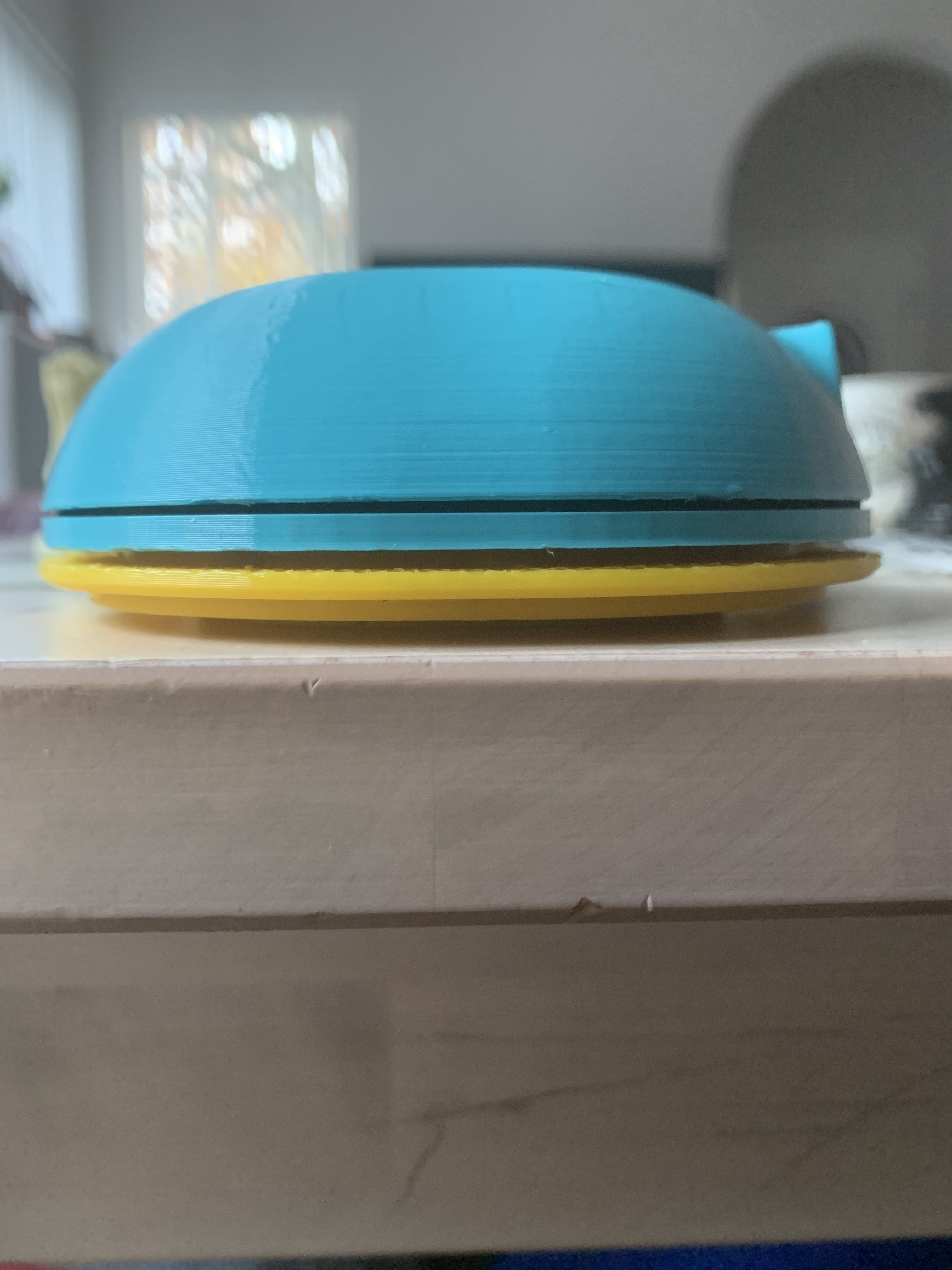
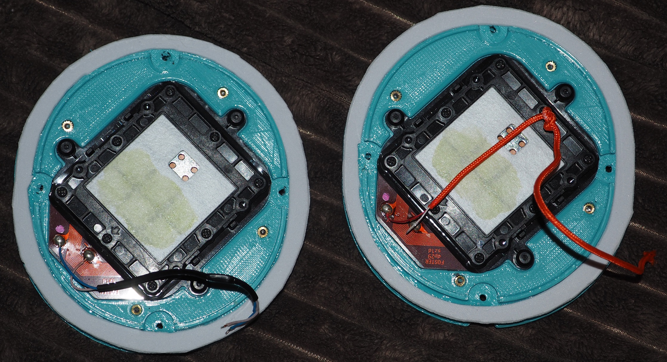
Open Alpha cups appear to fit original stock baffles. This would be a great option if you want to save time printing and finishing. I may try building a set with original mk3 baffle and another set with Open Alpha printed baffle + pad mount lip. Mk3 baffle has the pad lip built-in as one piece. The mk3 baffle is not necessarily better in terms of sound quality. The different physical dimensions and venting design could make it worse for all I know. Lazy man’s option. Definitely still requires a foam gasket for good seal. Will update if requires non-stock screws, Ive not actually tried screwing together yet.
Attachments

Last edited:
Aligns and screws with stock screws. The 3DP cup needed a little cutting (i used a drill) to clear slight excess filament over the screw post holes. If you replaced stock screws with self tapping screw then any post print cutting might be unnecessary.
Attachments


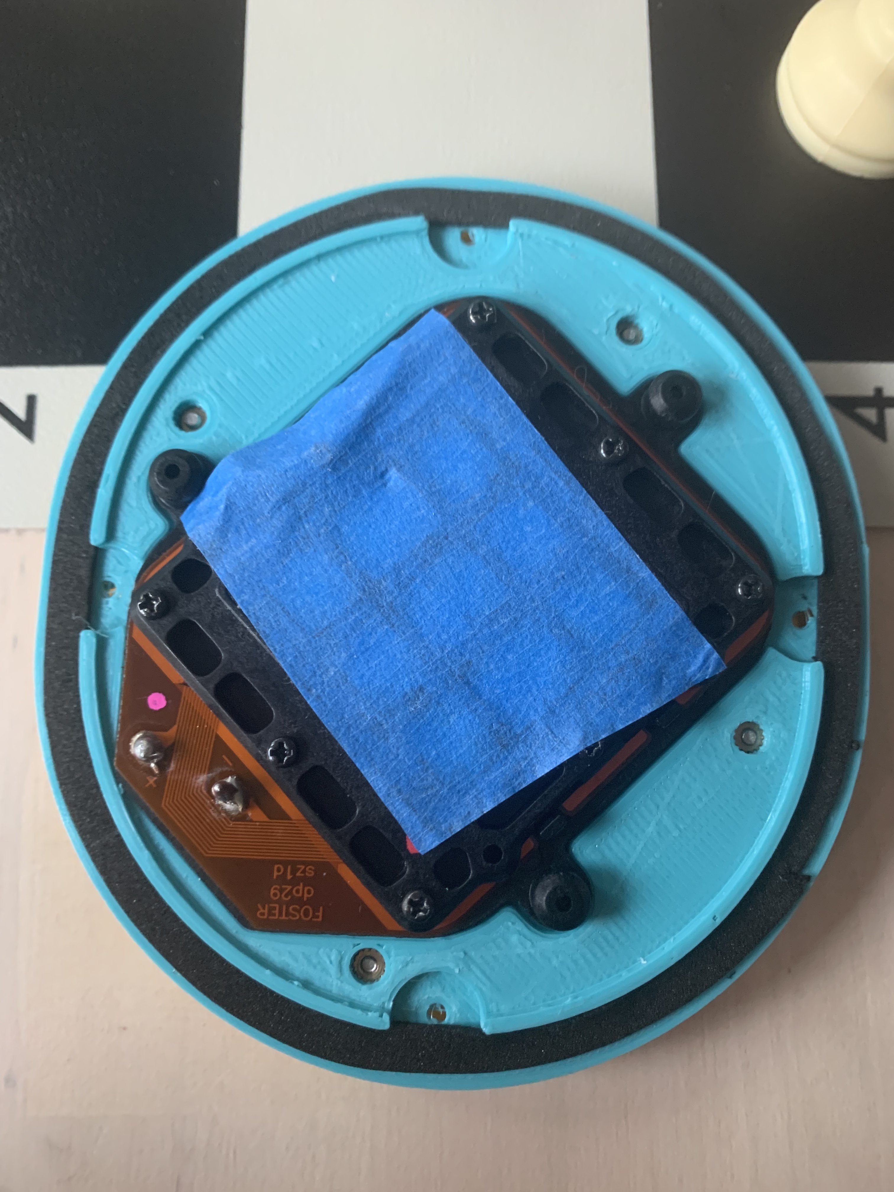
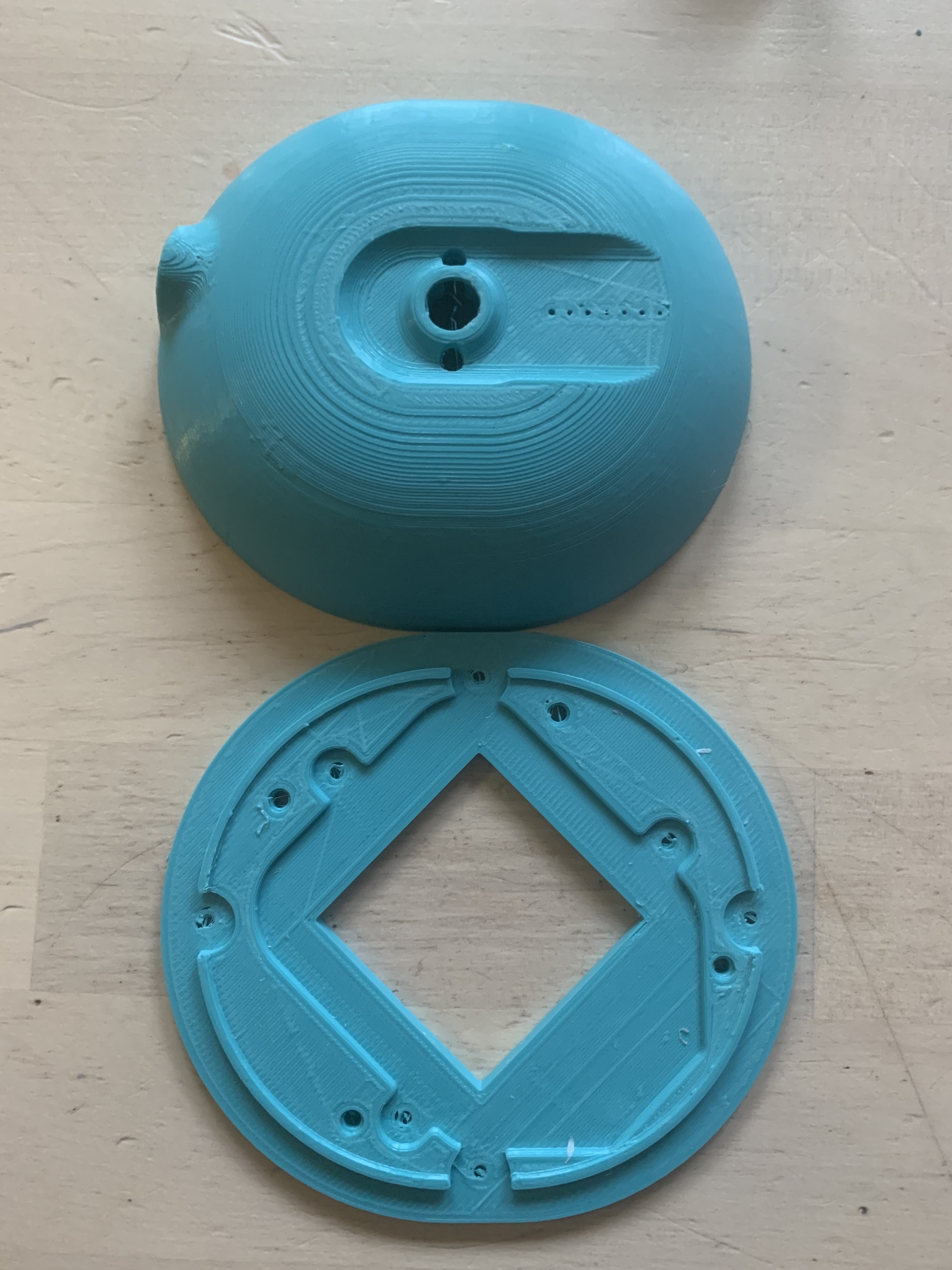
Cups and baffle fit together. I havent removed supports from pad ring yet.
Attachments
ThatHeadphoneGuy
New Head-Fier
is that the new audiophile thing to do? cup rolling?  Cheers mate!
Cheers mate! khbaur330162
Vintage Ortho Ninja 🥷
- Joined
- Aug 5, 2006
- Posts
- 2,010
- Likes
- 1,830
Here are the stl files for heated inserts guys:
Exactly as stock except using a 3.5mm connector, and implementing heated inserts obviously..
https://www.dropbox.com/sh/ddzghyfh2r1nj1k/AABnAwMfcxCW52jYTvR4MSwSa?dl=1
Ive included an stl for the front slider cover, as I managed to strip the thread from my original ones, so might come in useful to someone.
Inserting heated inserts into the cups for beginners: (skip this part if you know what you're doing here)
So I've used 2 different heated inserts on my build, these ones are highly recommended for inserting into the cup as they take a ridiculous amount of force to pull out:
https://www.amazon.co.uk/gp/product/B07PP2SDST/ref=ppx_yo_dt_b_asin_title_o09_s00?ie=UTF8&th=1
I used an old soldering iron (set to around 230) which did the job fine, I know there are special tools and soldering iron bits available for doing this, but I had no problem with an iron.
My method for the cup inserts is to have a perfectly flat piece of metal on a hard surface nearby, then one insert at a time, (if you're using the inserts I've linked to then they should sit nicely in the cup hole), gently place the soldering iron tip into the insert from directly above, dont push down, just use the weight of the soldering iron...when the insert is about 80% submerged quickly put the iron down and flip the cup onto the hard flat surface and push down hard, there will be enough heat to finish the insert and the result will be a perfectly straight, perfectly flush insert.
Inserting heated inserts into the baffle:
These are cheaper ones that are fine for mounting the ring to the baffle, as they are inserted from the cup side of the baffle:
https://www.amazon.co.uk/gp/product/B08H563S9W/ref=ppx_yo_dt_b_asin_title_o02_s00?ie=UTF8&psc=1
Use the same approach to inserting the baffle inserts as above, but because the surface of the baffle isn't flat, instead of flipping over onto a flat surface to finish the insert off, just have a small flat metal object to hand to finish the insert off when it is 80% submerged, again this ensures a straight, flush insert.
I had this set lying around so you dont need all of them, just the M2.5x3.5x3mm ones...remember these need to be mounted from the rear of the baffle, after you have inserted them let them cool down for a few minutes, and before doing anything slowly screw a longer 2.5mm screw all the way through from the same side you inserted them. This will push out any filament that might be blocking the insert and the hole when you mount the baffle.
The screws I have are from this set:
https://www.amazon.co.uk/gp/product/B075WY5367/ref=ppx_yo_dt_b_asin_title_o06_s00?ie=UTF8&psc=1
The screws used for mounting the ring to the baffle are M2.5x8mm
The screws used for mounting baffle to the cups are M2.5x6mm
All screws should be fitted with a M2.5x6x0.5mm washer, I can't link to the washers as I have an old selection box full of them and I have no idea where they came from.
Be careful if not using these exact screw lengths as you could screw straight through the cup.
As far as tightening goes, personally I keep screwing until I start to feel resistance, and then do a quarter turn more. Obviously it would still be possible to over tighten these, because you'll just start to crush the 3d material you used to print.
I felt it best to leave the driver mounting as normal, as without modifying the drivers themselves I couldn't see a way to improve this, so mount the driver to the baffle exactly as per the initial instructions.
Personally I've cut reusable silicone gaskets that sit between the ring and the baffle, and between the baffle and cup, if you dont go down this route then obviously seal/glue these parts as per the initial instructions.
Any questions then just ask, any improvements or suggestions are welcome.
Good Luck !
Edit: Sorry I should point out, in your 3d printers settings, set perimeters to greater than 2, I've set mine to 4 for extra strength around the inserts.
Just wanted to add my experiences using @gb160 instructions for heat inserts.
My soldering iron tip for the heat inserts would sometimes get stuck in the nut. When I'd try to pull the soldering iron tip out it would pull the whole nut out along with it. Be sure to have a small jeweler's Philips along with you to push the nut in and center it before it cools, or even better, try wiggling the solder iron in a circular fashion to loosen the nut and also get extra plastic to stick to the nut, then pull out, then finesse the nut with soldering iron to center perfectly. I'd practice with the baffle nuts first as the screws for pad rings actually pull the nuts into the baffle further when you screw them in so it's not a big deal. Also I think using 8mm screws for the baffle ring is spot on, I used 6mm and it is pushing it, 6mm is barely long enough and because there's not much screw actually in the nut you have a chance of striping the nut, you definitely want more threads into the nuts.
I set the heat inserts, and then you're supposed to screw the screws in all the way from the reverse side (inside the cups towards outside the baffle) and this pushes the excess plastic out so you can shave it with a razor or fine wire cutter, basically finish the hole and make it flush... Well when I was doing this for my second pair I actually BROKE three of the 6mm screws trying to free a couple of the holes, they got so tight the screws snapped (it did not take much force, btw). I believe it was a combination of setting the heat inserts very deeply this time (all the way to the glass table I have, as deep as they go) which fuse the plastic into one solid piece and mashed some into the heat inserts, but also some solder from my tip getting into the threads and mucking things up making threads extra tight. So be sure your soldering iron tip is PERFECTLY clean and maybe only set 1-2mm countersunk into the hole, don't go all the way friggin' down and mash the plastic into a solid piece like I did. My first set went smoothly, I was just being overzealous on second pair due to having short screws and trying to get the heat inserts extra deep.
Don't cheap out on the screws!!!! Those Chinese-ium "Black" screws you see in all the kits on Amazon have a tendency to BREAK if you tighten too much (doesn't take much force, tbh). I suggest buying 304 stainless steel screws just to be on the safe side.
Also, my friend @Philimon printed me the wrong pad rings for heat insert build (NO PROBLEM). So in my particular case --as well as some others Phil built OA parts for-- I will leave these directions for us:
First I inserted the heat inserts. After that I drilled a single pilot hole through the pad ring making sure the holes were lined up PERFECTLY with the baffles (drilling through one of the heat inserts with very tiny bit so as not to shave the threads). I drilled pilot holes with 3/64's inch bit, then drilled out the holes more with 5/64's inch bit, and 5/64" was perfect for M2 screws (we used m2 screws instead of m2.5, fyi). It's easiest to drill fully only one hole at first, actually installed the screw, then use that screw as a hinge to line up the other holes for pilot holes (this holds pad ring better while you drill the other pilot holes to make sure nothing shifts and everything lines up perfectly which is very important, you could even use some damplifier or blue tac to hold things in place better if you are scared). Then unscrew the one screw, drill all holes the rest of the way with 5/64" and make sure you scratch off any shavings near the holes to make sure the pad rings lay down perfectly flat on baffles, i.e. no light can shine through (glue might help to make a seal, such as E6000, but I left mine bare).
Last edited:
khbaur330162
Vintage Ortho Ninja 🥷
- Joined
- Aug 5, 2006
- Posts
- 2,010
- Likes
- 1,830
Ok, so I now have some experience with setting the heat inserts on cups. @gb160 linked to heat inserts and within the Q&A of them someone reported that they were 5.7mm tall. So I originally used m2x6x3.5mm heat inserts for the cups. A couple of them got pulled out when trying to screw into them and also one was set so deep I needed an 8mm screw instead of 6mm like suggested. Well, I had an idea. There are also m2x8x3.5mm heat inserts in the kit I bought. Longer = better? I installed these on a second pair of cups and they are much much better from what I can tell, they felt SOLID when I was screwing in a baffle to one of the cups to test.
-edit-
Not sure if links are working for you guys, I will also included item title, they are all on amazon:
This is the heat insert kit I purchased:
Swpeet 110Pcs 5 Values M2 M3 M4 M5 M6 Female Thread Knurled Nuts Brass Threaded Insert Embedment Nuts Hydraulic Welded Joint Injection Molding Assortment Kit Perfect for 3D Printing Injection Molding
https://www.amazon.com/Swpeet-Brass-Embedment-Thread-Knurled/dp/B08YYFS922
These are the screws I purchased:
DYWISHKEY 310 Pieces M2 x 4mm/6mm/8mm/10mm/12mm/16mm/20mm, Stainless Steel 304 Phillips Pan Head Cap Bolts Screws Nuts Kit
https://www.amazon.com/DYWISHKEY-Pieces-Stainless-Phillips-Screws/dp/B07W5J4WC9
I doubt that they are truly 304 stainless steel because they are not magnetic as far as I can tell, but they should be a fair bit stronger than some of the cheaper options on Amazon.
Just FYI, here is picture of orientation on the m2x8mmx3.5 heat inserts that I bought. The knurling goes DOWN so it seats as deep as possible, the thin portion points towards the screw.

You can countersink them a couple mm's in the hole, they hold very well it seems, and the 6mm screws still reach. Just be careful obviously and don't push too hard with the soldering iron because it can get to a point where it just plummets into the hole. You want it deep enough it grips the plastic, but not so deep the 6mm screws can't reach it. Obviously you need to tweak with your iron to make sure they are perfectly centered/straight, but it's not an exact science, so don't obsess over it, eyeball is good enough. Here is a picture of a few of them installed to give you an idea of the depth I used:

If you are wary of breaking a screw I suggest using m2.5 like originally suggested, these should never break when freeing the melted plastic from pad rings (fwiw I felt m2 was a good size)
m2.5 screws (hex screws, NOT Philips)
HELIFOUNER 420 Pieces M2.5 x 4mm /6mm /8mm /10mm /12mm /16mm /20mm /25mm, Hex Socket Head Cap Bolts Screws Washers Nuts Kit, 304 Stainless Steel
https://www.amazon.com/dp/B09WJ4WF9K?ie=UTF8&*entries*=0&viewID=&*Version*=1
m2.5 heat insert kit (has 4mm and 8mm which should be good for pad rings as well as cups)
Guard4U 420Pcs M2 M2.5 M3 M4 M5 Metric 15-Sizes Brass Female Thread Brass Knurled Threaded Insert Embedment Nuts Assortment Kit,Double Pass Knurl Nuts Copper Embedded Fastener
https://www.amazon.com/Guard4U-15-Sizes-Threaded-Embedment-Assortment/dp/B08R63KCS5
FYI, these heat inserts have a different kind of knurling from the ones suggested by @gb160 and used by myself, so YMMV. I have not used either of these products so buy with caution, or find suitable alternative yourself.
-edit-
Not sure if links are working for you guys, I will also included item title, they are all on amazon:
This is the heat insert kit I purchased:
Swpeet 110Pcs 5 Values M2 M3 M4 M5 M6 Female Thread Knurled Nuts Brass Threaded Insert Embedment Nuts Hydraulic Welded Joint Injection Molding Assortment Kit Perfect for 3D Printing Injection Molding
https://www.amazon.com/Swpeet-Brass-Embedment-Thread-Knurled/dp/B08YYFS922
These are the screws I purchased:
DYWISHKEY 310 Pieces M2 x 4mm/6mm/8mm/10mm/12mm/16mm/20mm, Stainless Steel 304 Phillips Pan Head Cap Bolts Screws Nuts Kit
https://www.amazon.com/DYWISHKEY-Pieces-Stainless-Phillips-Screws/dp/B07W5J4WC9
I doubt that they are truly 304 stainless steel because they are not magnetic as far as I can tell, but they should be a fair bit stronger than some of the cheaper options on Amazon.
Just FYI, here is picture of orientation on the m2x8mmx3.5 heat inserts that I bought. The knurling goes DOWN so it seats as deep as possible, the thin portion points towards the screw.
You can countersink them a couple mm's in the hole, they hold very well it seems, and the 6mm screws still reach. Just be careful obviously and don't push too hard with the soldering iron because it can get to a point where it just plummets into the hole. You want it deep enough it grips the plastic, but not so deep the 6mm screws can't reach it. Obviously you need to tweak with your iron to make sure they are perfectly centered/straight, but it's not an exact science, so don't obsess over it, eyeball is good enough. Here is a picture of a few of them installed to give you an idea of the depth I used:
If you are wary of breaking a screw I suggest using m2.5 like originally suggested, these should never break when freeing the melted plastic from pad rings (fwiw I felt m2 was a good size)
m2.5 screws (hex screws, NOT Philips)
HELIFOUNER 420 Pieces M2.5 x 4mm /6mm /8mm /10mm /12mm /16mm /20mm /25mm, Hex Socket Head Cap Bolts Screws Washers Nuts Kit, 304 Stainless Steel
https://www.amazon.com/dp/B09WJ4WF9K?ie=UTF8&*entries*=0&viewID=&*Version*=1
m2.5 heat insert kit (has 4mm and 8mm which should be good for pad rings as well as cups)
Guard4U 420Pcs M2 M2.5 M3 M4 M5 Metric 15-Sizes Brass Female Thread Brass Knurled Threaded Insert Embedment Nuts Assortment Kit,Double Pass Knurl Nuts Copper Embedded Fastener
https://www.amazon.com/Guard4U-15-Sizes-Threaded-Embedment-Assortment/dp/B08R63KCS5
FYI, these heat inserts have a different kind of knurling from the ones suggested by @gb160 and used by myself, so YMMV. I have not used either of these products so buy with caution, or find suitable alternative yourself.
Last edited:
CNC kitchen has some good inserts and soldering tips in his shop, check them out!
https://cnckitchen.store
https://cnckitchen.store
Longfellow78
100+ Head-Fier
- Joined
- Feb 8, 2014
- Posts
- 140
- Likes
- 67
Can anyone advise on tuning my open alpha please. I used the recommended akasa paxmate and cotton wool balls, and used the akasa to make the baffle as well. Aliexpress angled protein pads - like a mad dog clone. The build is very solid but There's not enough bass and the trebles are too forward and harsh. I have some T60rps with the mayflower baffles and the bass on those hits like a truck and the trebles are much better. The T60 actually sounds better to me, but I want to sell those and make the open alpha work.
The screw is fully removed so the bass port is open, which I thought boosted the bass. Replacing the t60 baffles with mayflower ones makes a huge huge difference, so I wonder if it's just my paxmate baffles are too puny. Any advice would be appreciated - thanks.
The screw is fully removed so the bass port is open, which I thought boosted the bass. Replacing the t60 baffles with mayflower ones makes a huge huge difference, so I wonder if it's just my paxmate baffles are too puny. Any advice would be appreciated - thanks.
From page 1:Can anyone advise on tuning my open alpha please.
- Apply foam or felt around the driver (ear side of the baffle). Wool felt has the most absorption across a broad range; if your headphone sounds hot, consider felt. Foams generally do a bit less.
- If you are not getting enough bass or mid-bass output, you may consider making a small perforation (e.g. a 3mmx3mmx3mm triangle) in the exposed paper. This is obviously a non-reversible action and should you not like it, may require additional modifications to the driver to re-balance it.
Another cheap one is to use some thin felt or dishcloth and use it like a liner for the inner wall from the earpad to eliminate reflections.
Experiment with the amount of cotton. Less is sometimes better.
Last edited:
khbaur330162
Vintage Ortho Ninja 🥷
- Joined
- Aug 5, 2006
- Posts
- 2,010
- Likes
- 1,830
Stock damping is bad. There was excess glue on mine to the point it made the treble very hot. By removing this damping, I did not alter bass extension at all yet treble is much much better. You can experiment with other damping options, however, none is really needed.Can anyone advise on tuning my open alpha please. I used the recommended akasa paxmate and cotton wool balls, and used the akasa to make the baffle as well. Aliexpress angled protein pads - like a mad dog clone. The build is very solid but There's not enough bass and the trebles are too forward and harsh. I have some T60rps with the mayflower baffles and the bass on those hits like a truck and the trebles are much better. The T60 actually sounds better to me, but I want to sell those and make the open alpha work.
The screw is fully removed so the bass port is open, which I thought boosted the bass. Replacing the t60 baffles with mayflower ones makes a huge huge difference, so I wonder if it's just my paxmate baffles are too puny. Any advice would be appreciated - thanks.
I would say that adding felt or foam around the driver helps the OA's with "hollowness," not necessarily treble, ime.
Longfellow78
100+ Head-Fier
- Joined
- Feb 8, 2014
- Posts
- 140
- Likes
- 67
Thanks Ok I will try some felt, my wife has some from her sowing stuff! I don't think I will make a hole in the paper just yet. I did pack the cotton wool pretty well in there, maybe there is too much. I'm certain I should be able to get the open alpha sounding better than the t60....
Longfellow78
100+ Head-Fier
- Joined
- Feb 8, 2014
- Posts
- 140
- Likes
- 67
Thanks - I'm not sure exactly what you mean by stock damping, on which headphone, and where was the glue? Thanks.
Users who are viewing this thread
Total: 3 (members: 0, guests: 3)
