Driving diaphragms with audio signal has been done, but it requires a low resistance membranes (aluminium foil) and high resistance stator. It's called inverted ESL. I'm using fully inverted ESL - one stator and 2 diaphragms, which are high resistance coated. Diaphragms are biased +360 and -360 V. Stator is a double sided copper, at 0V DC and is driven both sides with audio signal 220V AC. This is completely equal to 2 stators/1 diaphragm, except that you need double audio voltage in order to get 600V p2p. Linearity is the same, since both diaphragms are driven at the same time and mathematically they can be replaced with one driven from both sides. Actually they help each other to move in unison, since the air is trapped between them. Cons here are:
1. Double audio voltage - can't use and normal ESH amplifier without modding it or listen to a low level.
2. 4 equally tension-ed diaphragms - for me it's a big problem since I tension all separately.
3. Shielded cables for biases (it's a long and complicated story, remember my issue with channel separation?)
4. Need for thinner mylar - 3um are effectively around 4-5um - considering they move in unison and air is trapped between them (this is why I didn't want to use 11um kitchen foil") )
)
Advantages - as I see them in my personal opinion.
1. Extremely low drivers capacitance (in fact only cable capacitance is in the game). I think this is a good point to experiment with big ESL pannels
2. No need for dust/sweat covers (diaphragms are coated against the stator and air between them is sealed). But protective grills are very desirable.
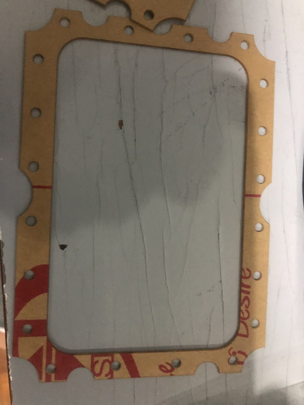
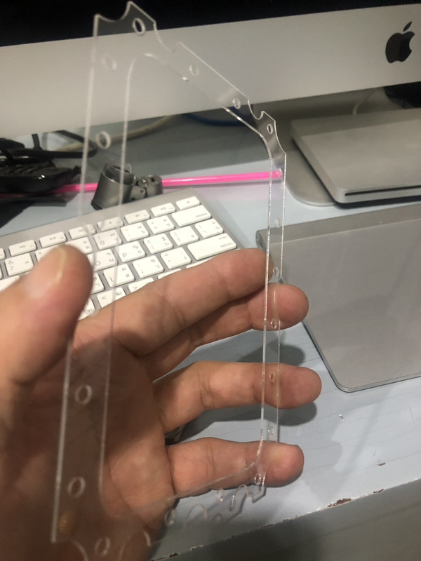
3. Spacers on which the myler is glued can be as thick as you wish - I use 1.6mm FR4
4. Just 1 stator to drill per cup
5. Most people say that single output amp is easier to build.
Not sure I mentioned all, some of the pros and cons can be justified either way, according to person preferences. For example - membranes are always attracted to each other and to the stator - for me they are relatively more stable, but need a bit more tension. On the other hand they can be pressurized in advance with some inert gas so they are flat, or even a bit swollen, but I don't think this can be done DIY.
I like how they sound, can't really tell a difference between both designs, may be a bit bassier (because of the effectively thicker membrane), which for me is great - I love bass. And yet again, I can't compare them to any high quality headphones, I just know they sound far better than anything else I own.
1. Double audio voltage - can't use and normal ESH amplifier without modding it or listen to a low level.
2. 4 equally tension-ed diaphragms - for me it's a big problem since I tension all separately.
3. Shielded cables for biases (it's a long and complicated story, remember my issue with channel separation?)
4. Need for thinner mylar - 3um are effectively around 4-5um - considering they move in unison and air is trapped between them (this is why I didn't want to use 11um kitchen foil
)Advantages - as I see them in my personal opinion.
1. Extremely low drivers capacitance (in fact only cable capacitance is in the game). I think this is a good point to experiment with big ESL pannels
2. No need for dust/sweat covers (diaphragms are coated against the stator and air between them is sealed). But protective grills are very desirable.
3. Spacers on which the myler is glued can be as thick as you wish - I use 1.6mm FR4
4. Just 1 stator to drill per cup
5. Most people say that single output amp is easier to build.
Not sure I mentioned all, some of the pros and cons can be justified either way, according to person preferences. For example - membranes are always attracted to each other and to the stator - for me they are relatively more stable, but need a bit more tension. On the other hand they can be pressurized in advance with some inert gas so they are flat, or even a bit swollen, but I don't think this can be done DIY.
I like how they sound, can't really tell a difference between both designs, may be a bit bassier (because of the effectively thicker membrane), which for me is great - I love bass. And yet again, I can't compare them to any high quality headphones, I just know they sound far better than anything else I own.
 ). I have wasted may be 30 membranes already until I reached around 140 Hrz free air resonance and +- 360V bias (only for these 84mm drivers). Any lower than 140 or higher than 360 slaps the membrane to the stator. With these setting I have measured the FR and it's amazingly flat from 30 up to about 700 Hrz. I'm still using toroidal transformers, which can't go lower than 30 - they saturate and the output signal is almost a square wave. Even so, the bass is very deep - I can feel the pressure in my ears without actually hearing it.