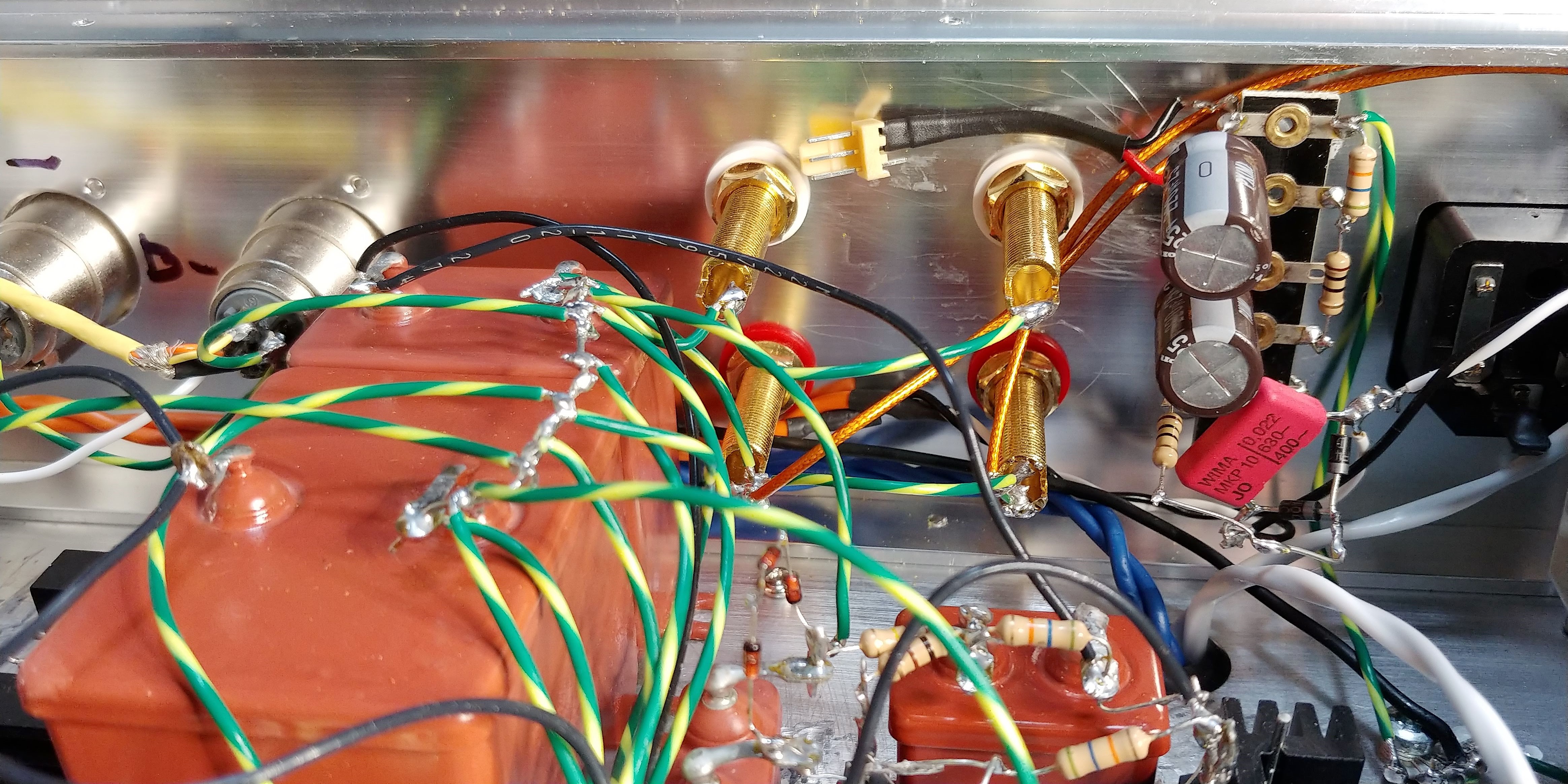
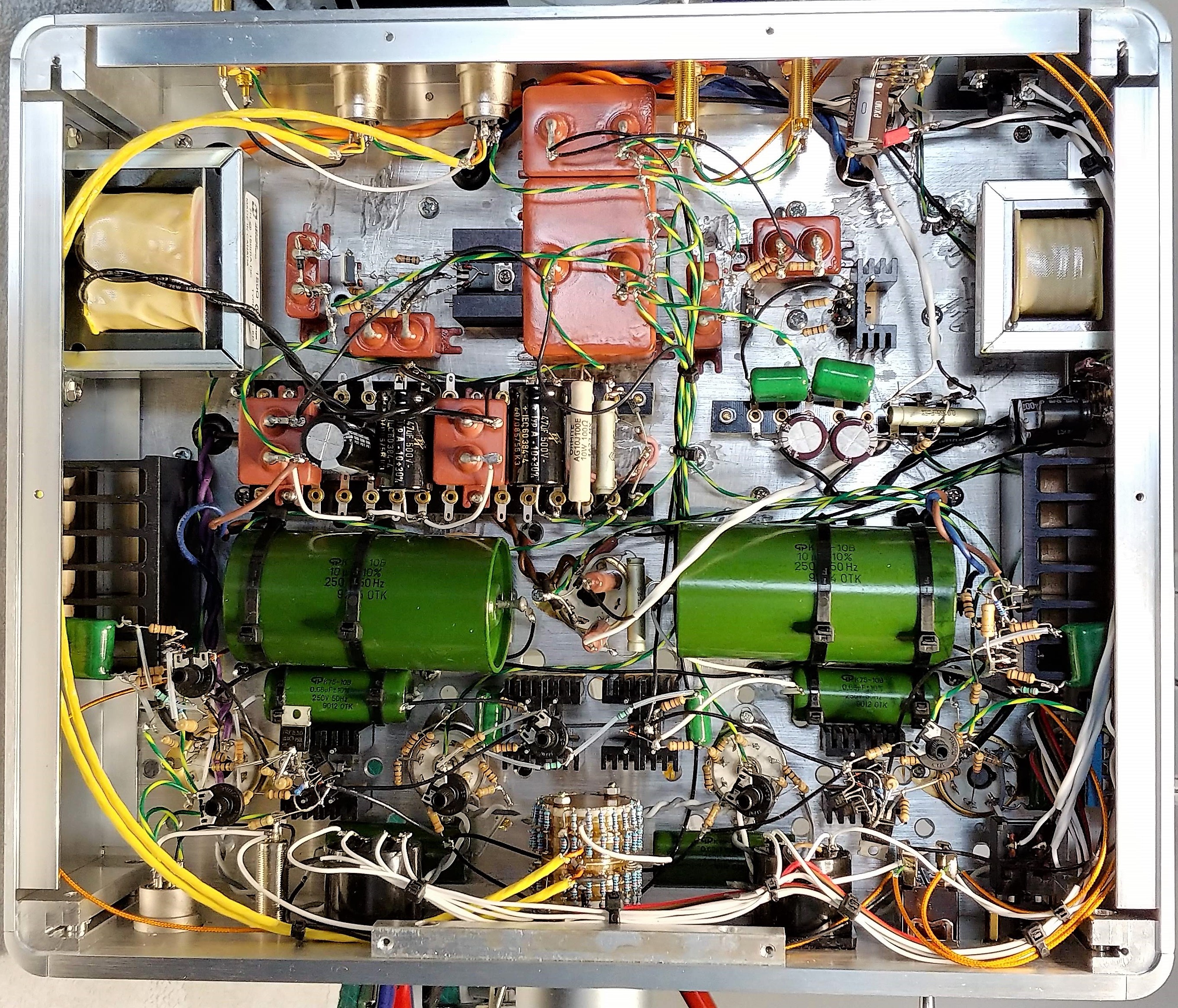
Not made any comparisons this time. Just decided to use the K75-10's and went with them. Mine (both the huge 10µ 250V and 680n 250V) are from the 90's. Don't know if you're thinking of some other cap? These are hybrid with both paper and lavsan in oil. There's definitely oil in them as they're very heavy and solid. Think they come in 250, 500 and 750V, not seen any other voltage ratings.
Yes I recall completely wrong. They have toxic oil inside. I should try and find the pdf of that russian cap catalogue I downloaded off some forum years ago and just post it here.
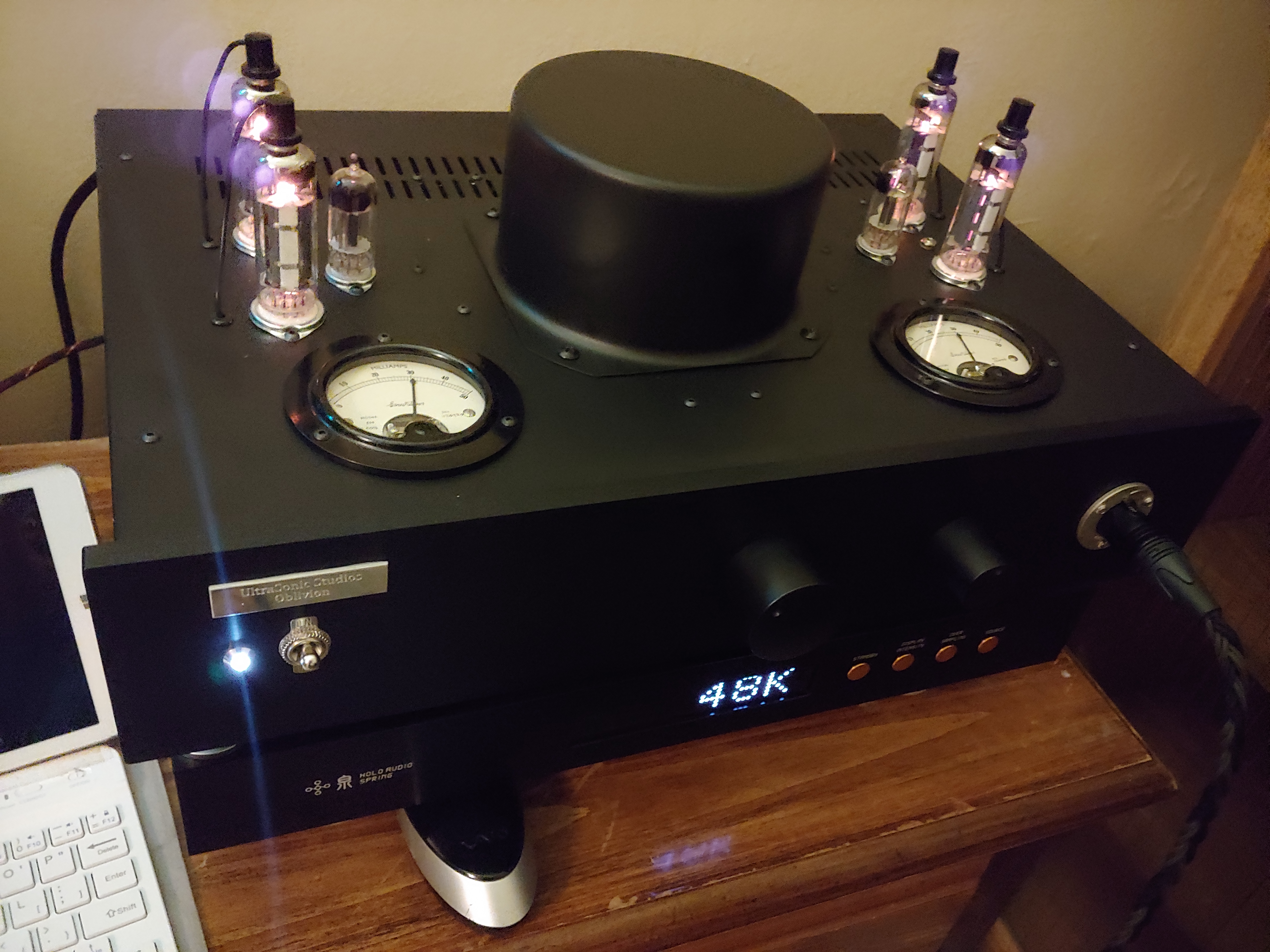
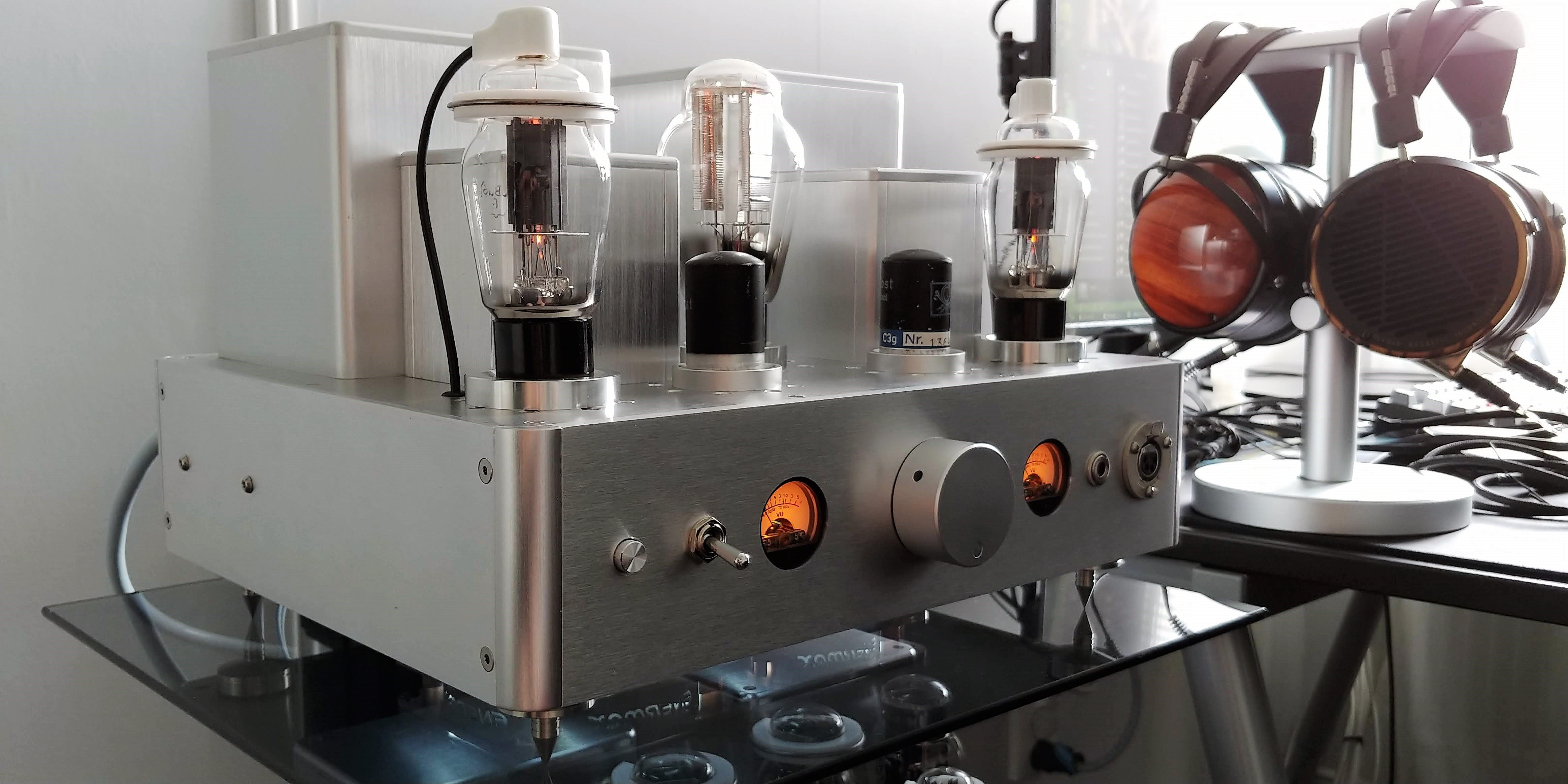
Might sadly be the case! You know I love my glowing tubes! C3G's are quite pretty ones naked. I might take a chance and buy another pair and strip them. If you're very careful it can be reversed!
One possibility is that if you use anti-oscillation methods, the extreme microphony might get under control. Stoppers on every pin, reduced gm etc. When used in pure voltage gain mode (input tube), gm doesn't matter at all so just toss it.
Will do a test for sure. I remember the output buffer breaking in the LTP when I did the power output test. This amp should not be so sensitive to clipping I think?
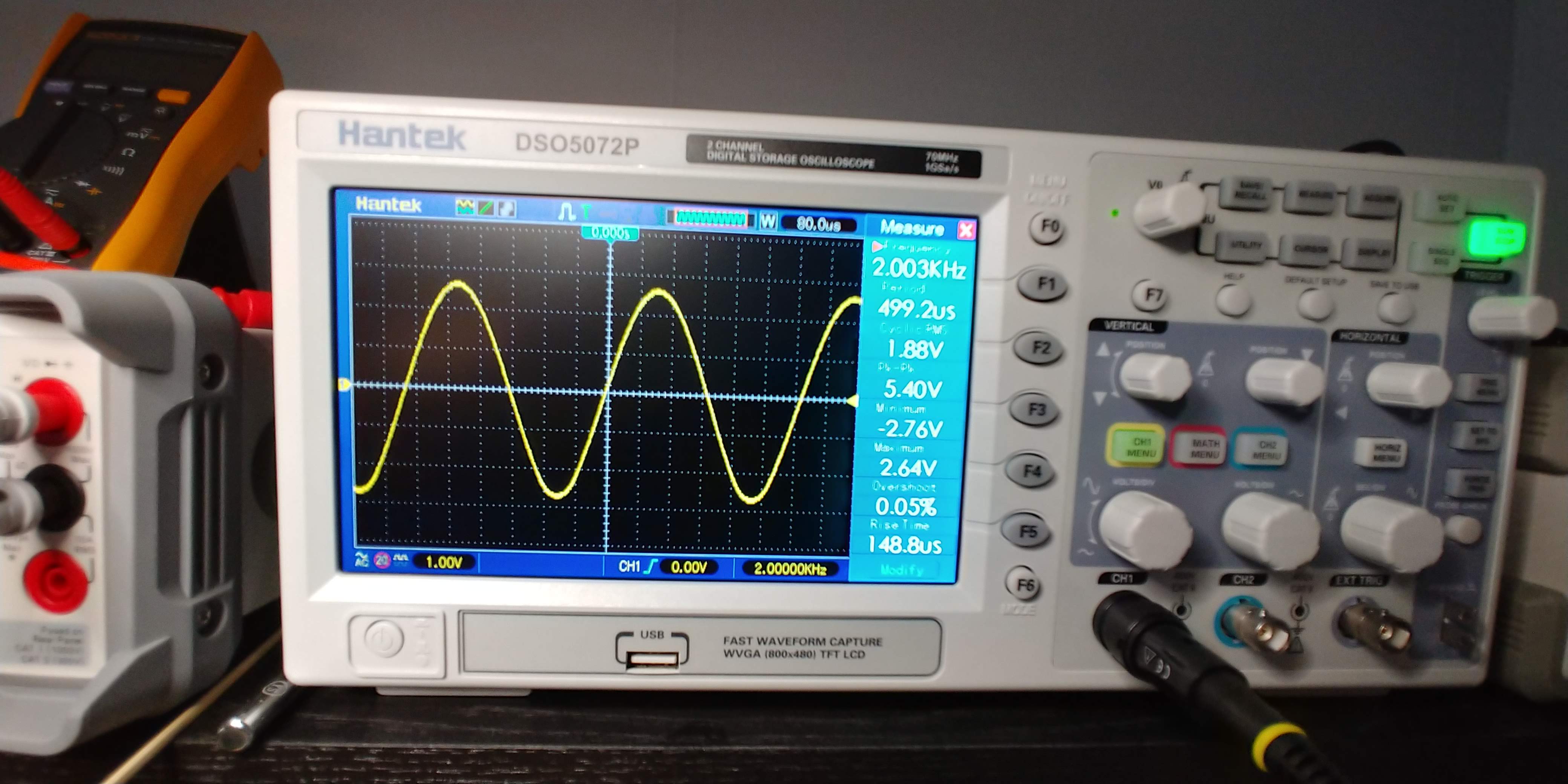
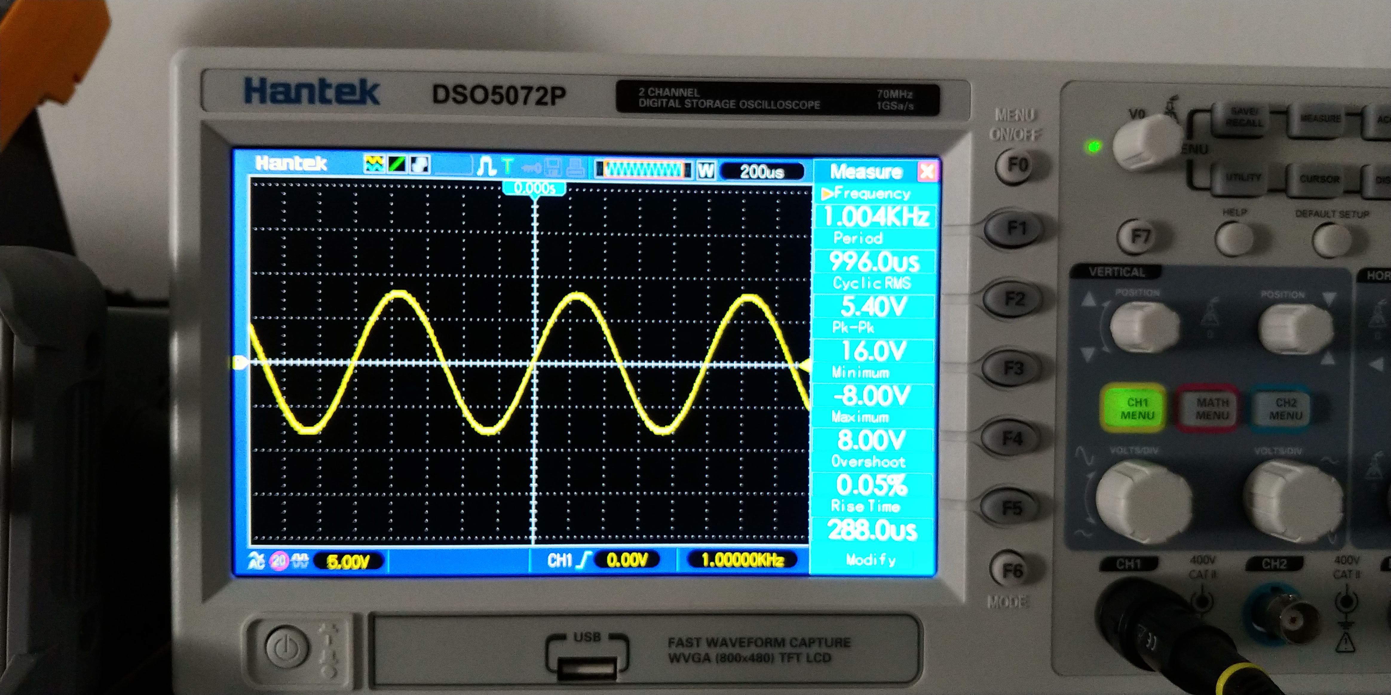
Probably not, but the CCS in parallel might break. Just increase volume veeery slowly and you should be ok. Use a higher f, maybe 2k or 4k; then the flat top of clipped wave is less like DC (because it's shorter in duration).
I think so, a long time ago, refresh my memory.
Human hearing cannot really make out the exact volume relations of peaks, unless they're grossly different in volume. If they're in the same general category of volume, you cannot tell which is louder.
Your can only produce the output power it can; after that it will clip. The output power is quite small, the amp clips a lot during transients. What matters is how the amp RECOVERS from that transient.
Now if you have a RC bias (cathode bias) somewhere, the bias circuit needs to recover from that transient. This takes time, during which the amp doesn't behave normally.
Worse yet if you have large NFB loops, spanning several gain stages; this takes a long time to stabilize again, during which time the amp behaves absolutely horribly. This is why when you use gNFB you want to have enough power capability for the loudest transients, even if your baseline power need is 0.1W RMS. That 100W transistor amp really needs that 100W in reserve, even if your baseline need is 0.1W (which it about is if you think that SE amp is loud enough).
There's lots more things inside typical tube amps that require some recovering time after a clipping transient.
Anyway, what happens if these things are taken care of? Well, the amp just clips the top off the transient, and then carries on just normally.
Your ears hear the music just continuing; they don't know how loud the transient was supposed to be, and even if the transient was there in full, they wouldn't be able to say in blind A/B comparison which transient is louder, the clipped one or the full one. They are both "loud", since they rise very fast up from the baseline. Ears detect the delta of the transient, (how "fast" the music sounds) not the amplitude (how high the wave peak is).
So the key to making the amp "fast" is investing in transient response and recovery. This means driving all kinds of capacitances from low impedance sources (grid, OT), not using bias methods that can be destabilized (caps need recharging time), having a flawless PSU.
If you want "fast" sound dealing with parasitic C is very important; if the signal has to "wait" while a poor current source is trying to charge a parasitic C, the crisp edge of the transient is lost. The voltage needs to be able to rise instantly. Ears detect delta, not amplitude of transient.
The last one is the biggest difference between the balanced amp and the SE amp (when talking about "speed"); since the balanced amp is constant current draw, it has a flawless PSU. The SE amp draws varying current, so it doesn't have.
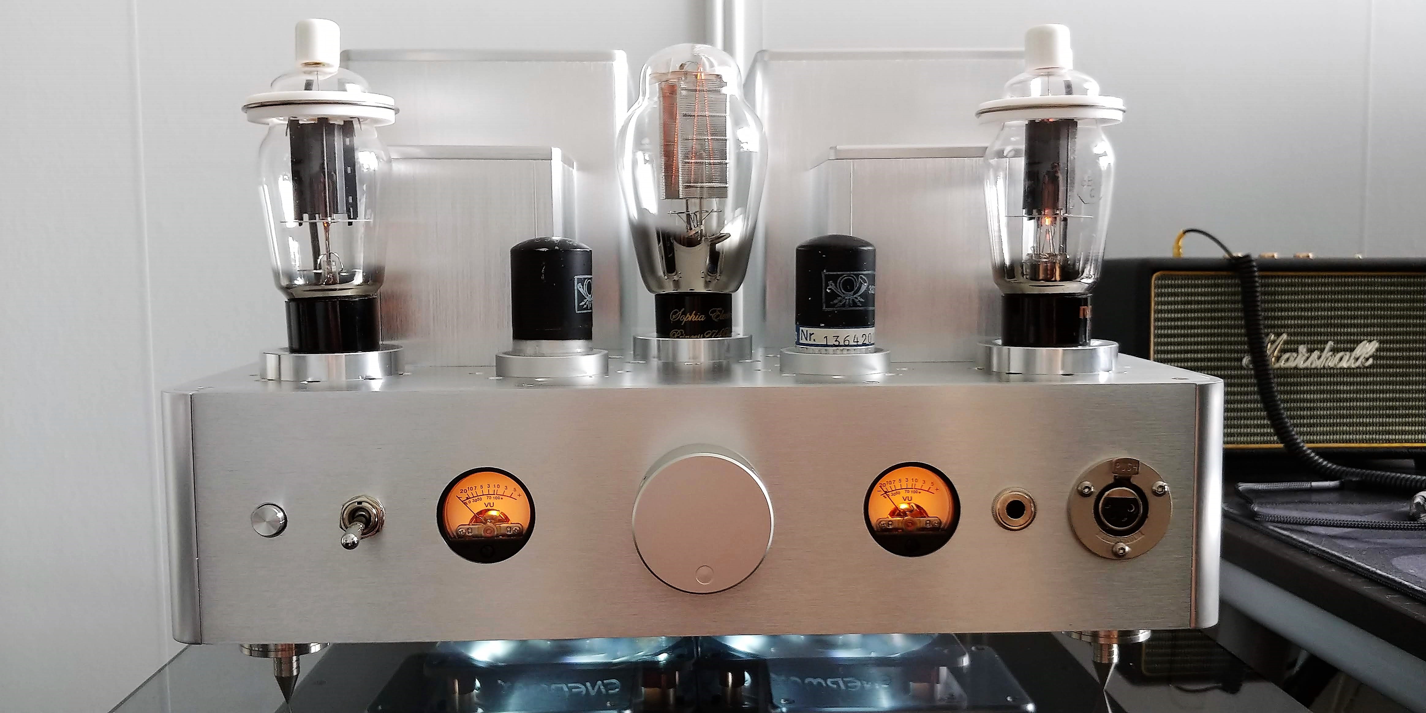
I agree! If you want "super high end" full balanced is the way to go. But after spending some time with this SE version I don't think it's "worse" than the balanced but rather "different flavor" if that makes sense. I really like it!
How would you place
1) IDH balanced amp
2) DH balanced amp
3) SE amp
4) modded LD
in relation to each other regarding sound quality. In different aspects of SQ ("speed", "realism", "microdetails" etc) the order of preference might be different of course.