Millett "Starving Student" hybrid amp
Jul 3, 2013 at 12:30 AM Post #6,586 of 7,277
Quote:
  First is the headphone delay worth putting in?  Lets say I have a friend fire this up while I'm away, I'd rather not lose some nice Sennheisers.
 
  Second, I've been looking at the e12 circuit and the simplified version from the HybridMax at http://www.diyforums.org/MAX/MAXe12.php .  If this is put into the system what then is the current load that the power supply needs to be able to output?  If this goes into the system, are two of them needed, one for each channel?
 
  Third, how well does the diode method of bypassing the headphones at startup / shutdown work?  (Seen here: http://www.head-fi.org/t/319231/millett-starving-student-hybrid-amp/5805#post_7413132)  Do the LEDs continue to blink indefinitely? 

 
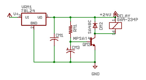
Sure, the e12 would help.  If you go with the e12, there would be 2 channels on the board.  If you build your own, you would replicate the circuit, it's for 2 channels as it's a DPDT relay.
 
I've not used the diode method to bypass.  I do have a LED with a series resistor to visually indicate when I should insert the headphones.  You'll still get a pop.  Also, I wouldn't short the output to ground with the diode.  I wouldn't bother with this for protection.  A visual reminder, sure.
 
I'm not sure how much the e12 draws, but I would guess no more than 40mA.
 
Jul 3, 2013 at 9:39 PM Post #6,587 of 7,277
Thanks Holland, 
  I think I've gotten this down but let me make sure I'm clear, and not doing something stupid.
  I'd put the modified e12 into the circuit (http://www.diyforums.org/MAX/MAXe12.php) with the power to the relay coming in across DM2 on the contact pins for the relay, while the L&R output from the amp (to the head phones) is coming in on the respective relay pins which get closed to the headphone jack when the relay closes?
 
 Second clarification, the e12 circuit calls for 12 to 30 V and says to draw the power directly from the power supply, as to have the e12 portion of the circuit start working when the amp is turned on.  However, the power supply is 48V.  Should the V+ terminal on the e12 then be ran in series with a resister to drop the voltage over the e12 to somewhere between 12 and 30V?

Thanks for the help!
 
Jul 3, 2013 at 10:27 PM Post #6,588 of 7,277
Quote:
Thanks Holland, 
  I think I've gotten this down but let me make sure I'm clear, and not doing something stupid.
  I'd put the modified e12 into the circuit (http://www.diyforums.org/MAX/MAXe12.php) with the power to the relay coming in across DM2 on the contact pins for the relay, while the L&R output from the amp (to the head phones) is coming in on the respective relay pins which get closed to the headphone jack when the relay closes?
 
 Second clarification, the e12 circuit calls for 12 to 30 V and says to draw the power directly from the power supply, as to have the e12 portion of the circuit start working when the amp is turned on.  However, the power supply is 48V.  Should the V+ terminal on the e12 then be ran in series with a resister to drop the voltage over the e12 to somewhere between 12 and 30V?

Thanks for the help!

 
In that circuit, you'd put the amp power into V+.  The circuit drops it down to 12V to drive the relay (QM1 and DM1 will drop to DM1's voltage spec, 12V zener means 12V output).  You do not connect the amp power rail to DM2.  Yes, you wire the amp output and the headphone jack to the relay pins (the normal closed pins).
 
No, no series resistor only.  You need to supply a voltage splitter.  A resistor divider will work.  There's already two on the Starving Student, to set the voltage for the gate of the output mosfet.  Replicate it (don't connect it to that point), with a 3rd divider (2 more resistors) to set the voltage you want.  Power the e12 circuit in parallel to the resistor that is connected to ground.  For a real Starving Student, that is roughly at 24V.  I haven't looked at the modified version with the 12AU7, but it will be over the heater voltage.
 
Jul 4, 2013 at 6:30 AM Post #6,589 of 7,277
As far as I'm aware an e12 will draw too much current for a voltage divider to work, the realy will draw continuously around 10mA (wi more consumption when the capacitor is charging) and a resistive divider is normally designed to run at about 1mA with e same current going through the top and the bottom resistors as it is used as a reference, not as a place to draw current. Personally I would be inclined to increase RM1's value by a factor of 1.5 or 2 and then just put a heatsink capable of a couple of Watts on the bd139 (it's a Zener controlled voltage regulator anyway) and just use that.

Cheers!
 
Jul 4, 2013 at 12:36 PM Post #6,590 of 7,277
Quote:
As far as I'm aware an e12 will draw too much current for a voltage divider to work, the realy will draw continuously around 10mA (wi more consumption when the capacitor is charging) and a resistive divider is normally designed to run at about 1mA with e same current going through the top and the bottom resistors as it is used as a reference, not as a place to draw current. Personally I would be inclined to increase RM1's value by a factor of 1.5 or 2 and then just put a heatsink capable of a couple of Watts on the bd139 (it's a Zener controlled voltage regulator anyway) and just use that.

Cheers!

 
Build it and find out.  It's not hard to tweak the circuit and power it with the power brick directly.  A voltage divider is just something that does what it does and has no restriction, it'll just burn some power.  The e12 circuit just needs voltage and some small current.  I'm not sure how much, haven't done the math and too lazy to do an analysis with pen and paper and looking up datasheets.
 
A series resistor may work too, perhaps about 68K, I'm not sure.  I had thought about just heat-sinking it, but figured it's not really necessary if you can burn off power in other parts.
 
After you build it, you can measure current draw and voltages at certain points.  Build it with a very long delay, so your DMM can settle.  You'll see active and inactive currents and voltages.
 
Edit: Ah, well, you made me get off my ass and take a look at some parts.  There's a 48V relay from Omron that I recalled.  You can "repart" the circuit to operate around that.
 
Jul 4, 2013 at 7:08 PM Post #6,593 of 7,277
Quote:
 
Build it and find out.  It's not hard to tweak the circuit and power it with the power brick directly.  A voltage divider is just something that does what it does and has no restriction, it'll just burn some power.  The e12 circuit just needs voltage and some small current.  I'm not sure how much, haven't done the math and too lazy to do an analysis with pen and paper and looking up datasheets.
 
A series resistor may work too, perhaps about 68K, I'm not sure.  I had thought about just heat-sinking it, but figured it's not really necessary if you can burn off power in other parts.
 
After you build it, you can measure current draw and voltages at certain points.  Build it with a very long delay, so your DMM can settle.  You'll see active and inactive currents and voltages.
 
Edit: Ah, well, you made me get off my ass and take a look at some parts.  There's a 48V relay from Omron that I recalled.  You can "repart" the circuit to operate around that.

We "reparted" (I prefer re-designed) the relay-delay for the MOSFET-MAX.  It uses a 24VDC relay.  The switching is much faster.  You can get a noticeable turn-on/turn-off thump with the lower-voltage relays (speed of contact closing, not the delay in the circuit).  At higher voltages, it becomes nothing more than a click with most headphones.
 
Higher voltage relays are more susceptible to arcing and burning the relay out over time, though, so we also changed the protection diode to a voltage suppressor.  Overall, the circuit is more simplified and works better (at least in the MOSFET-MAX and MiniMAX):
 
relay-delay.jpg

 
Full details are here: MOSFET-MAX Relay-Delay
 
Jul 4, 2013 at 10:20 PM Post #6,594 of 7,277
Quote:
We "reparted" (I prefer re-designed) the relay-delay for the MOSFET-MAX.  It uses a 24VDC relay.  The switching is much faster.  You can get a noticeable turn-on/turn-off thump with the lower-voltage relays (speed of contact closing, not the delay in the circuit).  At higher voltages, it becomes nothing more than a click with most headphones.
 
Higher voltage relays are more susceptible to arcing and burning the relay out over time, though, so we also changed the protection diode to a voltage suppressor.  Overall, the circuit is more simplified and works better (at least in the MOSFET-MAX and MiniMAX):
 
relay-delay.jpg

 
Full details are here: MOSFET-MAX Relay-Delay

 
That's pretty cool.  What accounted for the speed increase?  Probably the cap charging time?  There's probably about 200ms or so for the voltage to come up in the prior stuff.  I can't say I've noticed the arcing with higher voltage (24VDC, haven't tried the 48VDC relay), how did you discover that?  AMB's e12 uses 24V for the split rail relays.  I hadn't heard about problems with that, at least when I was active a few years ago.  I'm not sure if there were recent discoveries about that on his site.
 
Also, why not have a resister in parallel with CM3 to discharge faster?
 
Jul 4, 2013 at 10:40 PM Post #6,595 of 7,277
Quote:
 
That's pretty cool.  What accounted for the speed increase?  Probably the cap charging time?  There's probably about 200ms or so for the voltage to come up in the prior stuff.  I can't say I've noticed the arcing with higher voltage (24VDC, haven't tried the 48VDC relay), how did you discover that?  AMB's e12 uses 24V for the split rail relays.  I hadn't heard about problems with that, at least when I was active a few years ago.  I'm not sure if there were recent discoveries about that on his site.
 
Also, why not have a resister in parallel with CM3 to discharge faster?

My guess is the higher voltage.  If that causes a shorter cap charging time, then maybe that's it.
 
I haven't noticed arcing in these relays, either - they're sealed.
wink.gif
  However, I've seen plenty of it in my old model railroad days.  Turnouts are often run at 12V-16V with open coils.  (There are other methods to deal with it in that hobby.)  I think cetoole suggested it after reading the recommendations for the smaller relays used in the MOSFET-MAX input signal relay system, so it seemed a prudent thing to do on the headphone relay-delay.
 
The resistor idea is intriguing.  We have probably gone the other direction from AMB's e-12: toward simplicity and fewer parts.   However, the bump-on/bump-off scenario can leave a headphone unprotected if the delay is set on the short side.  So, anything to discharge that cap faster might be a good idea. 
 
Jul 4, 2013 at 11:18 PM Post #6,596 of 7,277
Here's a table I found from Tyco Electronics that details typical contact materials, the melt voltage, the arc voltage, and arc currents:
ContactMaterials.jpg

 
As you can see, we may be in the optimum range with all of these at 24V - some of them even at 12V (I don't know what the current is, either, but it doesn't look like it takes very much.).
 
Tyco describes the use of the protection diode (1N4148 in previous designs) and its result in holding up the relay coil:
"Some relay users connect a diode across the inductive load to prevent
counter voltage from reaching the contacts. When the relay contacts
open, the stored energy of the inductance recirculates through the diode,
not through the arc. While this is an acceptable method of protecting the
contacts, it does result in lengthened hold-up time of the inductive load."
 
So maybe the use of the suppressor diode is what speeds things up?
 
Jul 9, 2013 at 11:24 AM Post #6,597 of 7,277
I was just wondering whether there would be any repercussions for using a normal diode instead of an LED for the tube.
I find the glow kinda tacky, but using a huge resistor to dim it would be alright also.

If the voltage drop is the same, does it matter?
 
Jul 9, 2013 at 1:37 PM Post #6,599 of 7,277
Thanks.
 
So they're not actually part of the signal path?
 

Users who are viewing this thread

Back
Top