Originally Posted by c12mech /img/forum/go_quote.gif Would there be any issues with mounting the power supply in the enclosure and just wiring in direct instead of using the plug? I'm not sure about heat dissipation of the PS.
Heat may not be a big issue depending on the enclosure, but it would be a bad idea to do this. If you put the power supply inside the case that means you are running AC to the case. This can (and probably will) cause noise in your circuit, and could also be a safety issue.
If you want to build the power supply into the unit, you'd be better off using a transformer and DIY supply that is shielded/isolated to prevent hum, while of course following all safety protocols.
No problemo. I don't want to discourage you from trying - you'll learn something new in the process - but it's not as simple as just dropping it in. There are a couple people who have built their own supplies to use with the SSMH, but it greatly increases the complexity and cost, and given the "value" nature of the starving student it's probably better to spend that time/money on a higher quality amp like the MiniMax or otherwise (not to imply that the SSMH is a lower quality amp).
The 17EW8s showed up, so popped them in to the amp. Didn't switch the bias resistor though for lack of time.
Initial impressions are that they are a definite improvement over the 12AU7s previously in there
, although those were generics just labeled '12AU7 China'. Now those sound at least a bit veiled in comparison, especially in the midrange; there's a better sense of space and dynamics with the 17EW8s.
Someone please correct me if I'm wrong, but I don't think the tubes would be too affected by running them on 12V heaters, since effectively that's just dissipating less power in the heaters. The extra 7V drop over the MOSFETs is balanced out by a drop in the bias current from 150mA to ~105mA, so the amp still runs much cooler, and I'm not a fan of huge bias currents anyway. Perhaps that may (or not) compromise sonically, but (imo) 105mA is still plenty, especially with comparatively high-Z Sennheisers.
Originally Posted by blippster /img/forum/go_quote.gif The 17EW8s showed up, so popped them in to the amp. Didn't switch the bias resistor though for lack of time.
Initial impressions are that they are a definite improvement over the 12AU7s previously in there
, although those were generics just labeled '12AU7 China'. Now those sound at least a bit veiled in comparison, especially in the midrange; there's a better sense of space and dynamics with the 17EW8s.
Someone please correct me if I'm wrong, but I don't think the tubes would be too affected by running them on 12V heaters, since effectively that's just dissipating less power in the heaters. The extra 7V drop over the MOSFETs is balanced out by a drop in the bias current from 150mA to ~105mA, so the amp still runs much cooler, and I'm not a fan of huge bias currents anyway. Perhaps that may (or not) compromise sonically, but (imo) 105mA is still plenty, especially with comparatively high-Z Sennheisers.
Oh wow... this little circuit doesn't cease to amaze me.... so it works without changing the gate bias resistors!? I'll have to try it myself this evening!
I don't think the tube suffers any damage by running it's heater with a lower voltage. Did you measure those 12 volts across the tube heaters?
Originally Posted by the_equalizer /img/forum/go_quote.gif Oh wow... this little circuit doesn't cease to amaze me.... so it works without changing the gate bias resistors!? I'll have to try it myself this evening!
I don't think the tube suffers any damage by running it's heater with a lower voltage. Did you measure those 12 volts across the tube heaters?
Just measured with the DMM. I get a reading of 13.7V across the heater pins with the 17EW8, and ~13V for the 12AU7. Looks like they were being run a bit hard.
I think getting the exact voltage shouldn't matter too much in terms of getting the tube to operate, as long as the heaters are burning enough power to get the electrons free of the cathode (and of course, not pushing them hard enough to wear out prematurely).
Originally Posted by timmyGCSE /img/forum/go_quote.gif so does that mean the 17EW8 tubes can be used in place with no change?
That seems to be the case, indeed.
Quote:
Originally Posted by blippster /img/forum/go_quote.gif Just measured with the DMM. I get a reading of 13.7V across the heater pins with the 17EW8, and ~13V for the 12AU7. Looks like they were being run a bit hard.
I think getting the exact voltage shouldn't matter too much in terms of getting the tube to operate, as long as the heaters are burning enough power to get the electrons free of the cathode (and of course, not pushing them hard enough to wear out prematurely).
13 volts at the 12A_7 heater is quite alright. They're nominally rated at 12.6 heater volts. But what seems interesting to me from your post is that it's the MOSFET gate bias (the gate to source voltage) what determines the MOSFET source voltage, and NOT the tube heater voltage setting up a fixed MOSFET source voltage.
You see, what I'd thought would happen was that the MOSFET source would sit at ~18 volts (the 17EW8 tube heater voltage) and, with R2, R8 = 390 K the MOSFET gate would sit at ~17 volts; so the MOSFET wouldn't turn on.
But what's happening is that the MOSFET source voltage, sitting over the tube heater, get's 'clampled down' 4 volts below the gate voltage (~17 volts) thus the voltage you read across the 17EW8 heater, and thus the
MOSFET turns on and the amp works! Very nice !
Originally Posted by the_equalizer /img/forum/go_quote.gif <snip>
You see, what I'd thought would happen was that the MOSFET source would sit at ~18 volts (the 17EW8 tube heater voltage) and, with R2, R8 = 390 K the MOSFET gate would sit at ~17 volts; so the MOSFET wouldn't turn on.
But what's happening is that the MOSFET source voltage, sitting over the tube heater, get's 'clampled down' 4 volts below the gate voltage (~17 volts) thus the voltage you read across the 17EW8 heater, and thus the
MOSFET turns on and the amp works! Very nice !
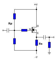
That's interesting. I was looking at it as akin to the 4 resistor MOSFET biasing diagram.
(image from Headwize, modified)
Here the source resistor Rs is replaced with the tube heater (18.9V/0.15A=125R?) to ground - the elegance of one less resistor per channel while providing the tube heater supply as well.
Well, I tested my 17EW8 with R2, R8 = 390 Kohms as blippster did and I can confirm it does work; the tube filaments barely light up, but the amp works alright.
My measurement of the heater voltage coincides with blippster's but certainly not the bias current, as I measured 140 mA flowing through each MOSFET (measured with both my analog VOM and my DMM). Considering the internal resistance of the meter, what we're seeing is the usual 150mA current.
So now I see that tube heaters do not behave like constant voltage sources, but rather like constant current sources!
My measurements, taken with my analog Kyoritsu FET VOM
PS voltage: ~47 V
Heater voltage: 12.5 V
MOSFET voltage: 34 V
drain-source current: 140mA
plate voltage: 31 V
cathode voltage: 0.84 V
current through each triode: 0.21 mA
So you can see that the current through the tube is ever so slightly lower than with the heater at 18 V (0.25) mA, which would make sense since the cathode is running cooler and thus emitting fewer electrons.
Originally Posted by the_equalizer /img/forum/go_quote.gif That seems to be the case, indeed.
ah ok cool, well I've had to shelve the minimax idea for now (
import taxes) so I may pick up a set of these. Cheers
edit: I get a fair amount of buzz from my SSMH..now, with my first SSMH I got no buzz when I was running it direct from my Sony mp3 but when I plugged it into my computer I got buzzing...any ideas? my interconnect isn't great, maybe I need a shielded one?
This site uses cookies to help personalise content, tailor your experience and to keep you logged in if you register.
By continuing to use this site, you are consenting to our use of cookies.