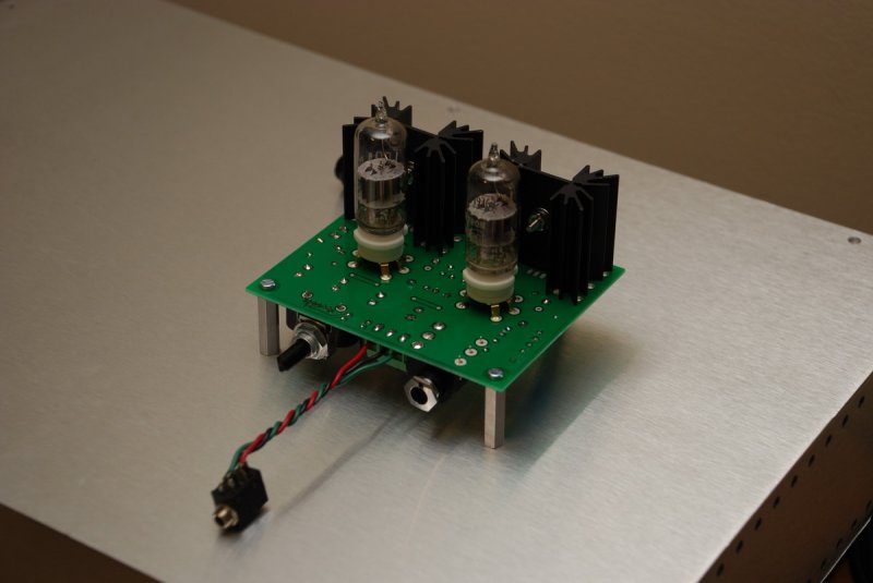
Millett "Starving Student" hybrid amp
Aug 5, 2008 at 6:17 AM Post #856 of 7,277
Quote:

Originally Posted by Postal_Blue /img/forum/go_quote.gif
I would try isolating the rca's from the case.


ok i may try this.

how about chopping the ground connection from the rca's to the copper ground plane? they would still be grounded through the case, but there would be no loop.
 
Aug 5, 2008 at 9:26 AM Post #857 of 7,277
I received a package from rs electronics today and was all excited about finishing my amp, until I discovered that they had messed up my order and sent just one mosfet
frown.gif


Is it OK to put the one fet in and turn on the amp with just one channel working? Or am I likely to mess something up. The only component missing would be the one fet, there are wires ready for it hanging out the case.
 
Aug 5, 2008 at 10:09 AM Post #858 of 7,277
Quote:

Originally Posted by Pandaman /img/forum/go_quote.gif
My amp has a pretty bad channel imbalance, with the left lower than right. Any reasons for this? and how can it be fixed?


Switch the tubes around, does the imbalance follow?
 
Aug 5, 2008 at 12:43 PM Post #859 of 7,277
Quote:

Originally Posted by adamus /img/forum/go_quote.gif
ok i may try this.

how about chopping the ground connection from the rca's to the copper ground plane? they would still be grounded through the case, but there would be no loop.


You ground plane is gonna be the better one to leave connected. Your hum may be caused by the more resistive path to ground through the case.
 
Aug 5, 2008 at 12:47 PM Post #860 of 7,277
Quote:

Originally Posted by ruZZ.il /img/forum/go_quote.gif
Switch the tubes around, does the imbalance follow?


Yes, unfortunately. I even tried another pair of tubes just then, still the same.
 
Aug 5, 2008 at 12:52 PM Post #861 of 7,277
Quote:

Originally Posted by Pandaman /img/forum/go_quote.gif
Yes, unfortunately. I even tried another pair of tubes just then, still the same.


Your response is a bit unclear. When you switch the tube does the imbalance switch channels, or is the left always the lower channel.
 
Aug 5, 2008 at 12:57 PM Post #862 of 7,277
Quote:

Originally Posted by n_maher /img/forum/go_quote.gif
Just another teaser photo of the first prototype of the pcb based version of the amp. Round two in underway so we're making progress.

101082098.jpg


Hows the prototyping going on this one? Im too lazy to P2P
smily_headphones1.gif
 
Aug 5, 2008 at 1:19 PM Post #863 of 7,277
Quote:

Originally Posted by Postal_Blue /img/forum/go_quote.gif
Your response is a bit unclear. When you switch the tube does the imbalance switch channels, or is the left always the lower channel.


Sorry bout that, its always the left channel.
 
Aug 5, 2008 at 1:41 PM Post #864 of 7,277
Quote:

Originally Posted by MrMajestic2 /img/forum/go_quote.gif
Hows the prototyping going on this one? Im too lazy to P2P
smily_headphones1.gif


What Nate said in that post - Dsavitsk is busy working on the 2nd iteration. I think everyone will be quite happy with what he's designed.
smily_headphones1.gif
 
Aug 5, 2008 at 2:01 PM Post #865 of 7,277
Quote:

Originally Posted by Pandaman /img/forum/go_quote.gif
Sorry bout that, its always the left channel.


It is almost certainly channel imbalance in your pot. You need to get further into the sweep of the pot most/all pots have the most imbalance issues at the lowest volume. A voltage divider on the input may be the best solution, or you could try output resisters as suggested by Germania.
 
Aug 5, 2008 at 2:23 PM Post #866 of 7,277
Sounds like PostalBlue has your problem diagnosed.

With the SSMH, Dsavitsk's and rds's method of using input resistors prior to the pot seem very helpful. I can't detect any downside, either - at least on the PCB version.

They are not a voltage divider, however. A voltage divider channels part of the signal to ground. The input resistors referred to above are only in line with each signal wire to the pot - Left and Right, one resistor each, nothing in the ground lead.

50K resistors for a 50K pot seem to be a good starting point. You should probably increase by additional 50K resistances from there, if you need it.

A voltage divider will mess up the input impedance of the amp. On the other hand, output resistors will probably need such a high resistance that dynamics will be lost.

So, I would suggest trying the input resistors. Dsavitsk is making that a regular feature of the PCB, by the way.
smily_headphones1.gif
 
Aug 5, 2008 at 3:41 PM Post #867 of 7,277
Quote:

Originally Posted by elliot42 /img/forum/go_quote.gif
I received a package from rs electronics today and was all excited about finishing my amp, until I discovered that they had messed up my order and sent just one mosfet
frown.gif


Is it OK to put the one fet in and turn on the amp with just one channel working? Or am I likely to mess something up. The only component missing would be the one fet, there are wires ready for it hanging out the case.


No problem at all. I would just make sure to disconnect the incomplete channel from 48v+ to avoid potential issues.
 
Aug 5, 2008 at 5:39 PM Post #868 of 7,277
Quote:

Originally Posted by Postal_Blue /img/forum/go_quote.gif
It is almost certainly channel imbalance in your pot. You need to get further into the sweep of the pot most/all pots have the most imbalance issues at the lowest volume.


That sounds right

Quote:

Originally Posted by Postal_Blue /img/forum/go_quote.gif
A voltage divider on the input may be the best solution, or you could try output resisters as suggested by Germania.


Two poor options

Quote:

Originally Posted by tomb /img/forum/go_quote.gif
With the SSMH, Dsavitsk's and rds's method of using input resistors prior to the pot seem very helpful. I can't detect any downside, either - at least on the PCB version.


Here's why and how this works, and why it is a better solution.

Generally, the load seen by the previous stage is a pot, which is an adjustable resistor divider to ground. At low volumes, the output can be pictorially though of as being closer to ground with the top resistor being larger, and at full volume, it is at the top.

pot1.jpg


Putting the resistor in front of the pot essentially elongates the top resistor of the divider pair. If, for instance, you have a 50K pot with a 50K resistor in front of it, you now have a 100K pot where the wiper, which sets the divisor's ratio, can only travel up half the length of the wiper. It also changes the divided ratio such that the same setting on the pot will yield less signal to the first stage of the amplifier. There is also some argument that it improves the quality of the resistor that is in the signal path, so actually sounds better than all but the best pots.

pot2.jpg


The full effect is that if you turn the amp all the way up, you have 50/50 divisor that sends, at most, half the signal to the amp when, with a normal pot only you would sent 100%. 50% of the signal is 6dB, which, for most instances is incidental. A 6db difference, especially at high volume, is almost inaudible. If you don't believe this, measure a normal log pot to find the point where it is 6dB down. It will likely be higher than you would ever turn up the amp.
 
Aug 5, 2008 at 6:29 PM Post #870 of 7,277
any other suggestion for my hum? isolated the jacks - no help. Touch the case - blissful darkness.
 

Users who are viewing this thread

Back
Top