Millett "Starving Student" hybrid amp
Jul 28, 2008 at 6:27 AM Post #766 of 7,277
Quote:

Originally Posted by scott_fx /img/forum/go_quote.gif
i built one chan of the amp so far, powered it up and it sounds really great; though, it's not very loud. at full volume it's not as loud as my ipod's internal amp. also, the volume control tops out at about half way. i'm not sure if these are related or not, could it be as simple as not having wired the pot correctly?

any advice guidance would be great. i can't wait to have this finished, i may build another one learning from my mistakes!


Not sure about the volume not being very loud, but I'd double check the wiring on the pot for the other problem and also make sure that it is an audio or logarithmic pot and not a linear pot (usually labeled 'audio' or the rating has a suffix of 'A'; linear has 'B' << I think that's correct, someone correct me if I'm wrong). I had a similar problem with a previous project where I had used a linear pot and the volume increased exponentially and topped at about 1/3 of the pot.
 
Jul 28, 2008 at 7:55 AM Post #767 of 7,277
Quote:

Originally Posted by elliot42 /img/forum/go_quote.gif
Not sure about the volume not being very loud, but I'd double check the wiring on the pot for the other problem and also make sure that it is an audio or logarithmic pot and not a linear pot (usually labeled 'audio' or the rating has a suffix of 'A'; linear has 'B' << I think that's correct, someone correct me if I'm wrong). I had a similar problem with a previous project where I had used a linear pot and the volume increased exponentially and topped at about 1/3 of the pot.


i did have the pot wired incorrectly and i did check that it was an audio pot. the volume is still lacking. I've tried the amp with cheapo low impedance earbuds as well and still had low volume issues
 
Jul 28, 2008 at 1:04 PM Post #769 of 7,277
Quote:

Originally Posted by scompton /img/forum/go_quote.gif
Would a blown mosfet cause the tube to burn bright and only a hum in that channel? Is there a way to test a mosfet short of replacing it?


tomb posted a link on how to test mosfets a few pages back. But more to the point, no I don't think that a blown fet would cause that behavior.

You might try posting some pictures of the wiring (clear, non-blurry pictures please) so that we can have a look at what might be wrong.
 
Jul 29, 2008 at 3:28 AM Post #770 of 7,277
Quote:

Originally Posted by n_maher /img/forum/go_quote.gif
tomb posted a link on how to test mosfets a few pages back. But more to the point, no I don't think that a blown fet would cause that behavior.

You might try posting some pictures of the wiring (clear, non-blurry pictures please) so that we can have a look at what might be wrong.


OK here's where I've been and where I am now with my build. As a total noob at DIY, I need help. I've made things worse just trying to take measurements
redface.gif


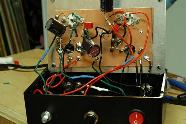
I finished wiring everything up yesterday and it turned it on with some cheap headphones plugged in. Everything worked fine except the pot was wired backwards. Fixed that and everything was fine. Here's a pic of what the whole thing looks like

DSC_6547.jpg


I decided to close it up. Powered it up and at first had a very bad channel imbalance. The right channel was low volume and had a loud hum. The hum was not effected by the pot. It was the same volume no matter what the pot was set at. The tube for the right channel was also glowing a lot brighter than the left.

In a PM, it was suggested I measure the voltage at the + side of C3 and C5. C5 was a little under 19V and C3 was over 30V.

Then I did something stupid. I tried to measure the input voltage at the power jack. The probe slipped and shorted between the pins on the power jack.

After doing that, the voltage at the power jack was fluctuation wildly. So fast that I couldn't read the numbers. I measured the PS and it measured 47.6V. I desoldered the power jack and plugged the PS into it. It measured 47.6V at the pins. I soldered the wires back on and the voltage again fluctuates wildly when I try to measure it.

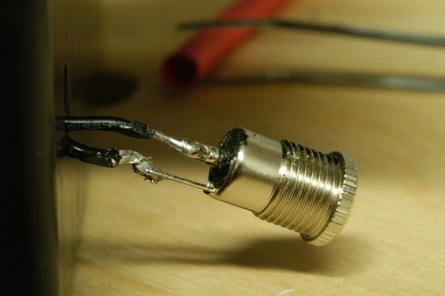
Here's a picture of the jack wired.

DSC_6544.jpg


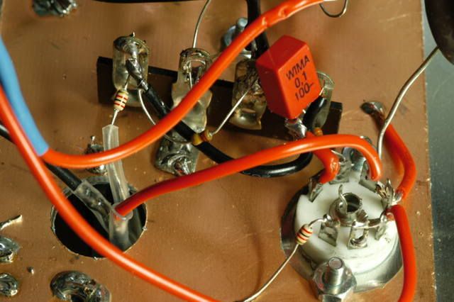
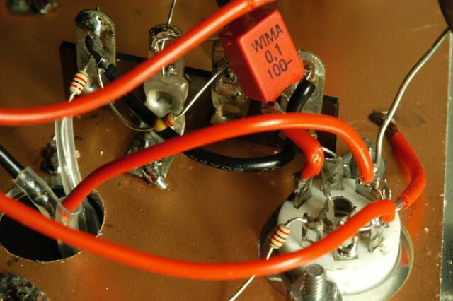
Here's some pics of the right channel. I also have pics of the left channel if you want to see them

DSC_6546.jpg


DSC_6542.jpg


DSC_6543.jpg


Any suggestions will be greatly appreciated. I was stoked when everything worked the first time. But I figure I'm going to learn more by screwing up like I have.
tongue.gif
 
Jul 29, 2008 at 4:36 PM Post #772 of 7,277
Good afternoon guys;

I got going with my build yesterday and after a few hours of casework and a few more hours of building I finished all the inputs and the right channel of the amp. I checked things one last time, plugged in, and flipped the switch to get nothing (not even smoke or flames, which I suppose is a good thing
rolleyes.gif
).

I went back to the schematic and figured out that I had not grounded the center pin on the 1/4" out. I made note of that and called it a night. This morning I fix that and while I compared my build to the schematic yet again I noticed I had not grounded R5 so I took care of that, as well. Upon firing it up again, still nothing. I confirmed that I do have 48vdc between the switch and the ground plane; however, I'm not seeing the err of my ways this time. Could anybody be bothered to take a look at what I've got and see if there is somewhere obvious I've gone wrong?

Pardon the mess (sorry) - I ignorantly designed the layout based on saving the logo on the top of the cigar case, rather than how it might be remotely practical to lay things out. On the mosfet yellow is pin 1, red is pin 2, etc.

http://rigshowcase.com/album.php?u_id=54UCagi
 
Jul 29, 2008 at 5:28 PM Post #773 of 7,277
Quote:

Originally Posted by Chipp /img/forum/go_quote.gif
Good afternoon guys;

I got going with my build yesterday and after a few hours of casework and a few more hours of building I finished all the inputs and the right channel of the amp. I checked things one last time, plugged in, and flipped the switch to get nothing (not even smoke or flames, which I suppose is a good thing
rolleyes.gif
).

I went back to the schematic and figured out that I had not grounded the center pin on the 1/4" out. I made note of that and called it a night. This morning I fix that and while I compared my build to the schematic yet again I noticed I had not grounded R5 so I took care of that, as well. Upon firing it up again, still nothing. I confirmed that I do have 48vdc between the switch and the ground plane; however, I'm not seeing the err of my ways this time. Could anybody be bothered to take a look at what I've got and see if there is somewhere obvious I've gone wrong?

Pardon the mess (sorry) - I ignorantly designed the layout based on saving the logo on the top of the cigar case, rather than how it might be remotely practical to lay things out. On the mosfet yellow is pin 1, red is pin 2, etc.

Seth Hochberg's Online Photo Album -


I'll take a closer look if I have time, but for right now:

* I think you need to ground the pot. I don't see any ground wires coming off from it.
* I'm not exactly sure, but you may still have the headphone jack wired wrong. I believe the two spring tabs make contact with L and R, while the Ground is probably one of those small tabs that's in contact with the sleeve and panel button.
* Pin 4 on the tube should be run to ground - I believe that's the one with the unconnected lead poking out near your "R" mark in the last pic (P1010018.jpg). If that's not run to ground, then a complete connection isn't made to the heaters. I don't think the tube will light.
 
Jul 29, 2008 at 5:45 PM Post #774 of 7,277
The headphone jack looks okay to me from image P1010015.jpg, although it is hard to tell for sure.

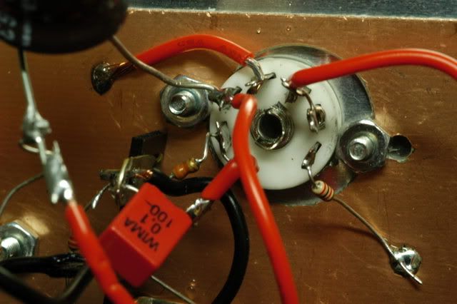
One thing I noticed is the wiring on the tube socket. In P1010017.jpg it looks like you have the cathode (pin 7) tied to ground, with a resistor across the cathode and one side of the heater (pins 7 & 4). The return on the heater (pin 4) needs to go to ground, and you need a 2k resistor between the cathode and the ground plane.

Take a look since the photos are sometimes hard to tell for sure, but this may be your problem.
 
Jul 29, 2008 at 6:55 PM Post #775 of 7,277
Thanks for the tips guys. I made the aformentioned corrections regarding pin 4's grounding and the resistor between pins 7 and 4 in addition to doublechecking the 1/4" out and wiring ground for the pot. Still a lifeless amplifier though. I do not see any visibly fried components, but I may just go ahead and build the second half keeping my mistakes in mind and see if perhaps that can shine some light on whats wrong.
 
Jul 29, 2008 at 8:34 PM Post #776 of 7,277
Quote:

Originally Posted by Chipp /img/forum/go_quote.gif
Thanks for the tips guys. I made the aformentioned corrections regarding pin 4's grounding and the resistor between pins 7 and 4 in addition to doublechecking the 1/4" out and wiring ground for the pot. Still a lifeless amplifier though. I do not see any visibly fried components, but I may just go ahead and build the second half keeping my mistakes in mind and see if perhaps that can shine some light on whats wrong.

Did you remember to add a ground wire to the third pin on the pot? If not, you'll need that for things to work.

I'd say that the tube may have seen some damage. I'm not sure what effect there is if the cathode becomes part of the heater circuit.
confused.gif


Before you try another tube though, I'd recommend slowly reviewing your wiring component by component until you are pretty sure that the rest of that channel is wired correctly.

Keep us posted.
 
Jul 30, 2008 at 3:12 AM Post #777 of 7,277
Quote:

Originally Posted by TimJo /img/forum/go_quote.gif
Did you remember to add a ground wire to the third pin on the pot? If not, you'll need that for things to work.

I'd say that the tube may have seen some damage. I'm not sure what effect there is if the cathode becomes part of the heater circuit.
confused.gif


Before you try another tube though, I'd recommend slowly reviewing your wiring component by component until you are pretty sure that the rest of that channel is wired correctly.

Keep us posted.


Yes, I did make sure to ground the pot.
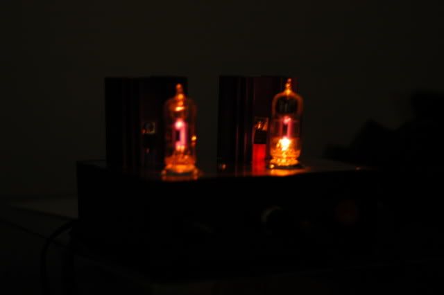
I'll give things another go-over and try one of the other tubes.

EDIT: This is probably a dumb time to ask this, but I was just thinking about the mosfet wiring. I did check the datasheets but could not find exactly what I'm looking for. The pinout for most TO-220 package devices is 1-2-3 from left to right if you are looking at the front (labeled) side of the chip. When I could not find a definitive answer either way as to the pinout of these specific devices I assumed they were the same. Are they not?
 
Jul 30, 2008 at 3:31 AM Post #778 of 7,277
I was wondering if you'd wired the mosfet in the right order -- there's a post in this thread where I discuss the difficulty I had in verifying the pin numbers. They are 1-2-3 left-to-right when looking at the mosfet on the side that is plastic, not metal. In other words, I think your assumption about pin numbering is correct.
 
Jul 30, 2008 at 4:28 AM Post #779 of 7,277
The pin outs were pretty clear to me from the data sheet on page 7. http://www.vishay.com/docs/91015/91015irf.pdf


Well I got mine working again. Both mosfets were fried. I think I fried the first when something shorted when I put tried to close the lid. I fried the other when I shorted the power jack. I removed both to test and they were shorted between pins 1 and 3. Fortunately,

I'm not really a starving student and, since this is my first build, I figured I'd screw something up, so I double ordered every thing except the PS. I figure I'll build something else in the future so it's not a total waste, plus I have spare tubes. I remember what a PITA tubes were when I was a kid and you could get them everywhere. Can't make a quick run to the 5 and 10 to buy tubes these days
wink_face.gif


I replaced the mosfets and rewired the electrolytic caps so I could put them in the bottom of the case before trying to close. I also put heat shrink on any lead that I thought might short. Powered it up and it sounds great. My only complaint is it's too loud, but that's my complaint with every amp I've tried.

DSC_6548.jpg


DSC_6549-1.jpg
 

Users who are viewing this thread

Back
Top