Stripping down your mZ2, part 3:
Re-manufacturing the in/out harnesses you're keeping.
Below are image of the wiring harnesses I made using the stock parts from a mZ2.
With little more time you could upgrade your RCA jacks, hook up wire, and attenuator, as you are making your minimized wire harnesses.
You could also add more preamp outputs, add more preamp inputs, and/or change the 1/4" jack to a 4-pin XLR.
So I'm not going to show you the "how to" with the upgraded parts I'm getting in next week. Likely I'll post a photo or three, but the process and technology I've outlined will work with any connectors, any wire, any attenuator, or for that matter, almost any component in your system.
You could even use the empty holes from where the binding posts were removed to reconfigure your mZ2 for up to three inputs and two outputs. Mike Percy has some very high quality silver contact toggle switches in a double throw triple pull that would allow you to do that.
Just follow the same rules for any ins and outs:
1. Less is more.
2. Isolate every in, out, and power wire.
3. Use twisted pairs of wires to cancel out common mode noise.
4. Keep as much space in between all wires and parts.
5. Make sure wires are away from parts that get hot (tubes).

Above is the inside of the 1/4" headphone jack with all the additional outputs removed. Note that both black/ground wires go to the same pin. If you were to replace this connector with a 4-pin XLR for balanced headphones each ground wire would have its own pin.
You'll note how the binding posts had a common ground but the wires coming form the main board have dedicated grounds for each channel. This is actually perfect if you wanted to replace the 1/4" jack with a 4-pin XLR.

Above is the stripped down input wiring harness along with the attenuator and no input selector switch. Note that I took one of the unused wires form the 2nd input for the 2nd channel's twisted pair. Note how I soldered that added ground wire to the ground tab on the RCA. Since both RCAs are grounded through the chassis, this one grounding tab should work just fine. The big advantage of adding the second ground wire was to lower noise floor with a classic common mode noise cancelling twisted pair (plus lower ground resistance).

This is a close up of the second ground wire at the RCA end. Note the second ground wire is red.

This is a close up of the stripped down attenuator on the end of the input wire harness. Note how on the R side it says "L in" and how that far right red wire is the 2nd ground I added.
Note those pins at the output of the attenuator. They connect to females on the main board. They are SO bad I can't believe it. I could barely put the pins on the output wires from the attenuator back into the females. They were VERY lose. My recommendation will be to remove those pins/females and hard wire solder the wires exiting the attenuator directly to the main board.
Of course this will make it a real PIA to reassemble and I wouldn't recommend doing it until one of the last steps in your mZ2 upgrade.

Above is a photo of the stripped down DC power input. Not only did I remove the on/off switch (the ZOTL LPS has a power switch), but I removed all that wire that ran parallel to the sensitive input signal wires.
Just like with the input from the attenuator, I recommend hard wiring the DC input as well. And also like the attenuator input, hard wiring inputs and outputs should be among the last things you do.
In my last re-assembly I'll be removing the DC input jack and replacing it with a strain relief that will allow the DC power cable to be hard wired to the main board plus eliminating two low quality DC power connectors.

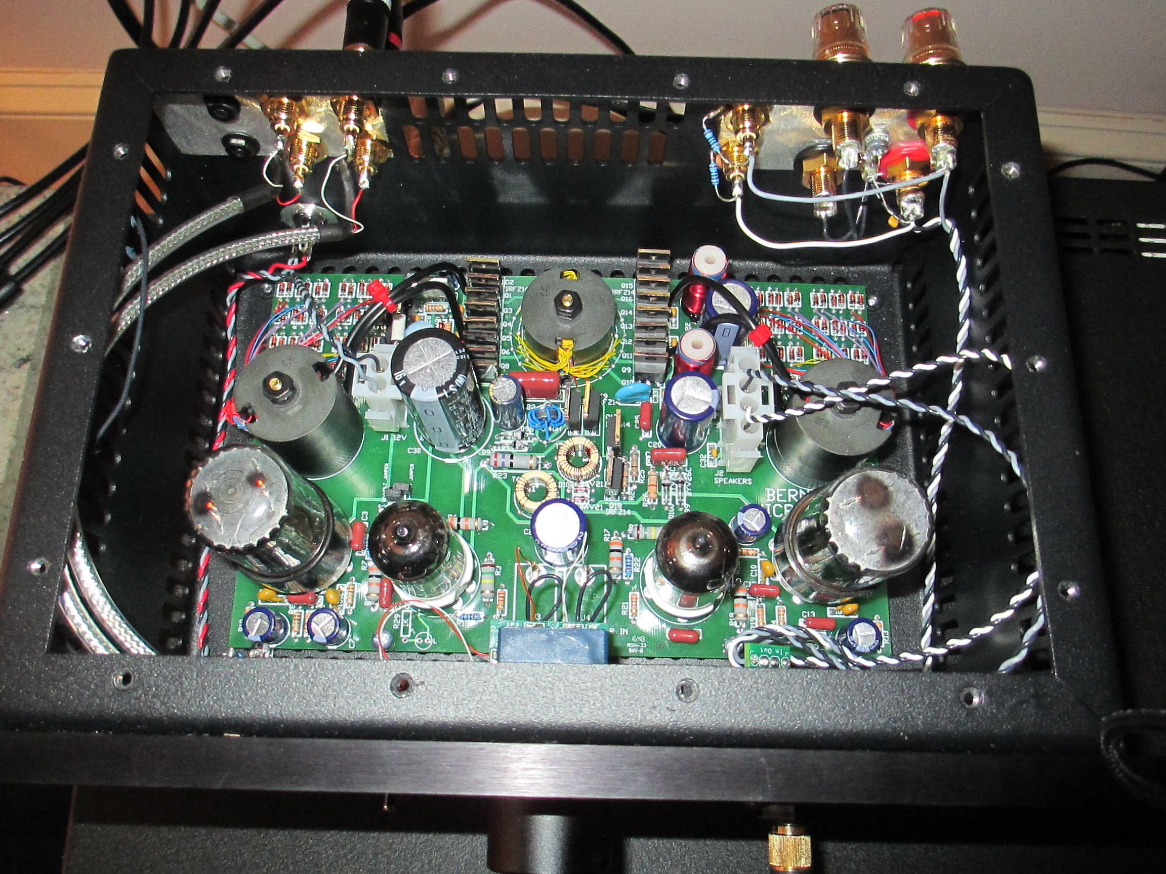
Above is a photo of the L side with fully stripped down inputs and wiring. Note that the L and R twisted pair are kept separated. Note that I put the R connector on the R and the L connector on the L as opposed to the high/low stock configuration. Note how the twisted pairs are away from everything.

Above is a photo of the stripped down output wire harness reinstalled. Note how the twisted pairs are both positioned away from each other and away form the hot output tube. This is one more connector that I recommend hard wiring at the final assembly of your mZ2 upgrade.

And finally the photo above has all the connectors, wires, switches, and face plate that were stripped off this mZ2.