Little Dot MK8SE / MK6 Super Mods (All verified mods are on first page)
Nov 24, 2018 at 6:42 AM Post #3,526 of 4,154
Hi klnglim!

I see you are still trying to sort out your amp. I can't be much help as I don't know exactly what you've done but I would go back to basics and double check a few things:

your traces new and old - your repairs to the board look excellent
your parts - are the specs the same. It is easy to misread some parts names, for example I mistook a .68R for a .68K resistor, also I used the wrong type of diode, both of which could have stopped the amp working. Are your parts all up to spec, the right way round etc.
wires all connected correctly.

I double and triple checked mine recently and still missed a few things!

All pretty basic but a mistake at this stage will be critical. It is difficult to know what's wrong when you have done so much.

When you've got the amp up and running you must complete all the upgrades to date, that way your amp will be pretty spectacular lol!
:).

Now I try other method, use good quality jumper cable as prototype style, there are a lot spaghetti wiring around, this project will finish soon.
All the resistors have changed to Dale & Mills, some electrolytic caps replaced with Nichicon audio grade, only power supply caps remain unchanged
Some Diodes have replaced with 5 Watts instead of 1 Watts, 2 rectifier changed to brand new 2W10 model
Mundolf EVO & EVO oil replace all WIMA caps, coupling and WCF
WIMA MKS2 replaced all the mini caps artound op-amp and gain switch
Overall Can be said 90% of components include gain switch, op-amp, potentiometer, fuses, Voltage regulator, MOSFET, NPN PNP transistors, headphone protector relay & 2 sets uA meter inside this tube amp is brand new
May be sound like I m a bit over spend all those parts, actual reason is I can get those parts replacement with very low price.
Because of those super cheap low cost parts, so why not replace all with brand new, right?
Beside new parts replacement, the ground shortage issue inside the PCB also had already been fixed.
The board have already been cleaned with Methal Spirit few times as well. The reason I seldom use ISO Alcohol is the board felt a bit sticky after dry and uncomfort with finger touch.
Hopefully, If this amp is successful to turn on, of course I will post to share.
If still no luck cant turn it on, then I'll have to work and study harder again until successful result show
Have to learn from Edison spirit : There are no failure in entire life but only to learn and find the best way to work it out! That means never give up! LOL
 
Last edited:
Nov 24, 2018 at 9:43 AM Post #3,527 of 4,154
Now I try other method, use good quality jumper cable as prototype style, there are a lot spaghetti wiring around, this project will finish soon.

Sounds like you have a handle on the situation!

Do you have a new chassis for the all that wiring, at least this method will allow easier fault finding and rectification.

I don't know why you have fluctuations in power, the only thing I can think of is a broken connection, or diode or transistor faults. Do you have the correct diode in for the headphone relay for example.

I hope you can get help to fix this soon.

:).

Edit: Quote by Albert Einstein: “Failure is success in progress”
 
Last edited:
Nov 24, 2018 at 11:50 AM Post #3,528 of 4,154
Sounds like you have a handle on the situation!

Do you have a new chassis for the all that wiring, at least this method will allow easier fault finding and rectification.

I don't know why you have fluctuations in power, the only thing I can think of is a broken connection, or diode or transistor faults. Do you have the correct diode in for the headphone relay for example.

I hope you can get help to fix this soon.

:).

Edit: Quote by Albert Einstein: “Failure is success in progress”
May be u are right about the Diode broken connection, since last time I found one of the 100V/5Watts Diodes which near transistor PNP trace was disconnected, I guess that's the reason to cause one of 120R resistor began smoke and right side uA meter malfunction then damaged.
All 3pin in/output have replaced with silver twisted cable and later all power cable from transformer will be rearranged as those are the worst thin crap quality cable inside the amp.
I had repainted the chassis with few level of shinny piano black finish colour as well as clear polish spray paint protection, so there will be no more LD MK8SE logo, no more any number or letter word will be seen
By the way, this whole tube amp machine and all the component has been tear apart, solder/desolder and PCB board taken in /out a lot of times by my own hand.
The original PCB board is quite strong and really good quality except all the copper traces & lines
are too weak, come off very easily
Since started troubleshoot from the sparkly short suddenly seen till now whole machine already been tear apart and re-assembly, the cost of spending actually not much (roughly around AUD100 I guess) but a lot of clock time wasted. I also learned a lot of electronic knowledge and very familiar about almost every single piece of component inside this amp. (I even can tell every parts has been soldered inside the PCB. LOL)
 
Last edited:
Nov 26, 2018 at 2:17 AM Post #3,529 of 4,154
I would rather stick with what I have already tried, ie. silver wires than use shielded copper as you did, at least in this area, because of what I have already found though
Yeah but for me I wanted change that input wire so best shielded was a silver plated. I only recommend for input stage.
For output cable it was best to with no plated types.

Did you notice any sonic improvements with your wire changes?
No.
No sonic changes for those power tramsistor wires as expected.

May I ask can Tube NOS Voskhod 6N1P-EV replace those 6H30P tube?
Here's the website
No.
Easiest way to check tube comparability & similarity is Google the data sheet.

Hi Maxx! It's been a long time, I m still troubleshoot and hard work on my MK8SE. I had completed several times unsoldered, resoldered and cleaned the board, unfortunately till now still fail to turn it on.
Left meter light on with "0" reading, Right meter no response at all, of course no sound at all, furthermore unstable voltage reading everywhere and sometimes one 120R/5W resistor near power supply smoke
Very obvios sign of PSU problem.
Most likely not full voltage.
Must test voltage.
Key areas of concern are break in the trace from top board to bottom, completing a center groundpoint from big power resistor area to the power transistor area.

Most likely failure are diode burn & resistor burn when the PSU not have proper voltage (half the PSU power reaches the power transistor area).

The second meter will never kick in if the PSU is at fault.

I didn't want to change 6H30p, just want to get some knowledges differential among those tubes
For you I only recommend rolling driver tubes, not power tubes, but there are differences still with the power tubes from the sovtec (more neutral) compared to the other ones (more bassy).

May be u are right about the Diode broken connection, since last time I found one of the 100V/5Watts Diodes which near transistor PNP trace was disconnected, I guess that's the reason to cause one of 120R resistor began smoke and right side uA meter malfunction then damaged
This area always a concern.
If the trace ia not broken from that area to the 4 big caps & power resistors (full voltage should be measured), then the issue usually solid-state failure(diode or power transistor).
Also check proper "NPN/PNP placement and wiring.
 
Nov 28, 2018 at 3:38 AM Post #3,530 of 4,154
Yeah but for me I wanted change that input wire so best shielded was a silver plated. I only recommend for input stage.
For output cable it was best to with no plated types.


No.
No sonic changes for those power tramsistor wires as expected.


No.
Easiest way to check tube comparability & similarity is Google the data sheet.


Very obvios sign of PSU problem.
Most likely not full voltage.
Must test voltage.
Key areas of concern are break in the trace from top board to bottom, completing a center groundpoint from big power resistor area to the power transistor area.

Most likely failure are diode burn & resistor burn when the PSU not have proper voltage (half the PSU power reaches the power transistor area).

The second meter will never kick in if the PSU is at fault.


For you I only recommend rolling driver tubes, not power tubes, but there are differences still with the power tubes from the sovtec (more neutral) compared to the other ones (more bassy).


This area always a concern.
If the trace ia not broken from that area to the 4 big caps & power resistors (full voltage should be measured), then the issue usually solid-state failure(diode or power transistor).
Also check proper "NPN/PNP placement and wiring.
PNP NPN, diodes and resistors brand new checked,however this time both meter light on togather, left side reading 30 and right side over maximum,
then the right side meter damage when I shut off the amp straight away.
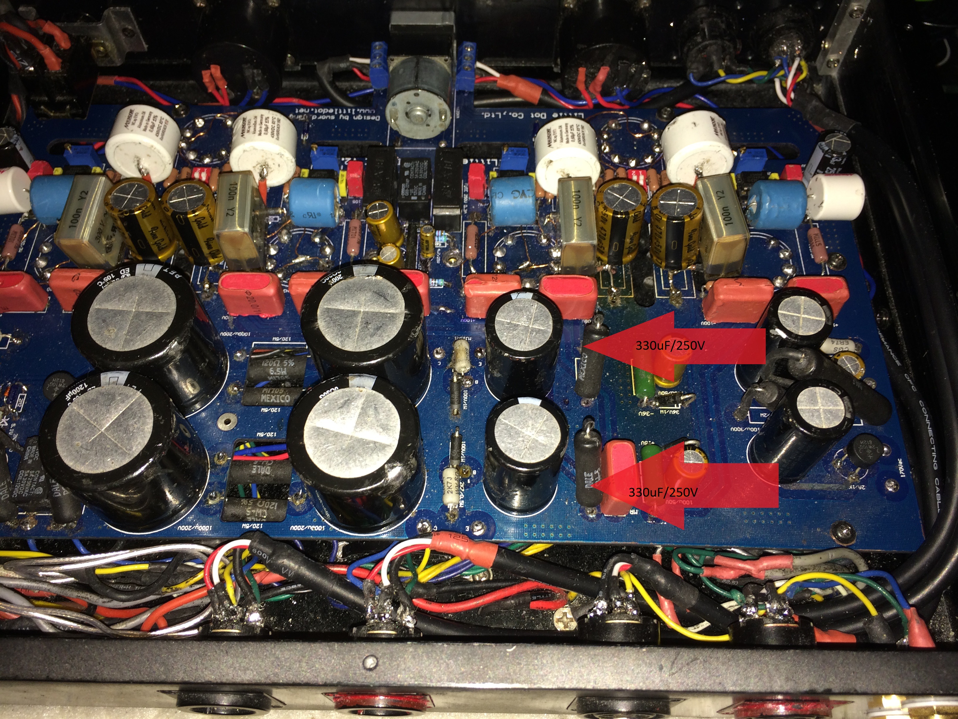
After found the problem and fixed for the cause of meter damage, I tried to turn on the amp again, another problem come again, both meter light on togather and only left meter read 30, right meter read nothing, then suddenly smoke come out from PSU caps 330uF/250V..
I turn off the amp again then later checked on all those diodes and resistors, none of those components have any error.
I had also already checked all the wiring, cant find any shortage and no error connection.
Unfortunately I cant take any voltage reading as I turn off the amp immediately when seeing smoke out from the caps
Have any idea what is wrong or why the PSU caps smoke?
 
Last edited:
Nov 29, 2018 at 6:14 PM Post #3,531 of 4,154
Have any idea what is wrong or why the PSU caps smoke?
Yes
Heat & smoke is usually from the resistor.
Caps usually bulge and blow up so be careful.

So check to see that those polarized caps are in the right direction, as well as those diodes.
I personally never seen smoke caps .
If you upgraded the diodes higher at watt, check also they are 100v I recall or they may not act like zener at designed voltage.
 
Nov 29, 2018 at 6:27 PM Post #3,532 of 4,154
PSU pic:
Screenshot_2015-06-02-13-44-07-1.jpg
 
Dec 1, 2018 at 7:17 AM Post #3,533 of 4,154
PNP NPN, diodes and resistors brand new checked,however this time both meter light on togather, left side reading 30 and right side over maximum,
then the right side meter damage when I shut off the amp straight away.
After found the problem and fixed for the cause of meter damage, I tried to turn on the amp again, another problem come again, both meter light on togather and only left meter read 30, right meter read nothing, then suddenly smoke come out from PSU caps 330uF/250V..
I turn off the amp again then later checked on all those diodes and resistors, none of those components have any error.

I think you have a problem on the left side as well, that left meter reading of 30mA doesn't sound right.

What diode are you using for the headphone relay?

Edit: While you have the amp switched off it might be an idea to work backwards from the output XLR's to see if there is any grounding issue, grounded wire connections are very difficult to see.
 
Last edited:
Dec 1, 2018 at 8:32 AM Post #3,534 of 4,154
I think you have a problem on the left side as well, that left meter reading of 30mA doesn't sound right.

What diode are you using for the headphone relay?
From PSU, I Have changed Diodes 15V, 36V & 100V from 1 Watts to 5 Watts power handling, both relay are using Diodes1N4007.
Both rectifier remain the same 2W/10 & transistors are MJ15024/MJ15025 (All brand new and no problem so far)
All the meter nearby red caps are original WIMA MKP10 0.22uF/250V.
All meter & caps polarity installed & checked are 100% correct.
Yesterday try to turn on, both meter light up togather but left meter read from 30mA jump to Max after a few seconds and right meter OmA.
When seeing the meter act unnormal, I straight turn off the amp immediately to avoid the current damage my meter again.
After a while, I desoldered & checked PSU every each of component, have just found one capacitor 100uF/450V leg is broken from deep inside, not sure whether is this cap cause an issue yet?
The funny thing is everytime I try to turn on the amp always cause me feel scarry & worry as both meter act strangely, make myself confuse & question why?
 
Dec 1, 2018 at 8:55 AM Post #3,535 of 4,154
From PSU, I Have changed Diodes 15V, 36V & 100V from 1 Watts to 5 Watts power handling, both relay are using Diodes1N4007.
Both rectifier remain the same 2W/10 & transistors are MJ15024/MJ15025 (All brand new and no problem so far)
All the meter nearby red caps are original WIMA MKP10 0.22uF/250V.
All meter & caps polarity installed & checked are 100% correct.
Yesterday try to turn on, both meter light up togather but left meter read from 30mA jump to Max after a few seconds and right meter OmA.
When seeing the meter act unnormal, I straight turn off the amp immediately to avoid the current damage my meter again.
After a while, I desoldered & checked PSU every each of component, have just found one capacitor 100uF/450V leg is broken from deep inside, not sure whether is this cap cause an issue yet?
The funny thing is everytime I try to turn on the amp always cause me feel scarry & worry as both meter act strangely, make myself confuse & question why?

That rectifier diode sounds right from memory, that is the one I misread from the board markings.

Yes, every time I switch on after modifications I have a nervous breakdown lol!

Have you switched on again after your cap leg issue? I also had this issue which caused me some problems similar to you with meter readings going haywire. When you bend cap or resistor legs don't bend them near to the cap body or else they may break.

If you still have problems you could try checking the grounding issue I mentioned in the previous post, also check the resistances of everything while your amp is off. Can help to highlight the problem areas.
 
Dec 1, 2018 at 9:05 AM Post #3,537 of 4,154
HI Maxx, from picture above, can I upgrade those 2 caps 330uF/250V to 1000uF/250V ? Cause I have those big caps size fit perfectly

Yes, and they will be better.
 
Dec 2, 2018 at 1:04 PM Post #3,538 of 4,154
The funny thing is everytime I try to turn on the amp always cause me feel scarry & worry as both meter act strangely, make myself confuse & question why?
If both meter come on then definitely error in the area near the time delay for the second meter.
It is at bottom corner.
Check that it is same exact value as the original tall cap.

Also,
Check the relay by that rectifier (that switch power) for a mistake in resistors connection that is under it.


HI Maxx, from picture above, can I upgrade those 2 caps 330uF/250V to 1000uF/250V ? Cause I have those big caps size fit perfectly
Bigger cap will cause slight current surge for the NPN&PNP, but they should be able to handle it if you upgraded them to the latest versions which I assume you did as they do not make the original power transistors anymore..
You should be ok since you upgraded the watts of the doides & resistors..

Make sure the Dale wirewound resistors have continuity with unit off and ohmmeter.

Then you need to check the bridge rectifiers for proper rectification because your cap got burned(?)
Whichever one that was should be check & or replaced.
 
Dec 4, 2018 at 11:31 PM Post #3,539 of 4,154
If both meter come on then definitely error in the area near the time delay for the second meter.
It is at bottom corner.
Check that it is same exact value as the original tall cap.

Also,
Check the relay by that rectifier (that switch power) for a mistake in resistors connection that is under it.


Bigger cap will cause slight current surge for the NPN&PNP, but they should be able to handle it if you upgraded them to the latest versions which I assume you did as they do not make the original power transistors anymore..
You should be ok since you upgraded the watts of the doides & resistors..

Make sure the Dale wirewound resistors have continuity with unit off and ohmmeter.

Then you need to check the bridge rectifiers for proper rectification because your cap got burned(?)
Whichever one that was should be check & or replaced.
Yes, and they will be better.
Hi guys! I would like to introduce capacitors discharger which is very useful for DIY members,
this built is come from my own idea several months ago, it just need multimeter voltage test, connect with a piece of resistor in parallel so to show the caps is fully discharge, 100% accurate and safe.
It costs cheap, simple and easy to make, all you need is multimeter, 2 pair banana plugs and a piece of 56K/5 Watts resistor. (Picture example below)

IMG_9416.JPG IMG_9417.JPG IMG_9419.JPG IMG_9421.JPG IMG_9422.JPG
 
Last edited:
Dec 5, 2018 at 12:22 AM Post #3,540 of 4,154
If both meter come on then definitely error in the area near the time delay for the second meter.
It is at bottom corner.
Check that it is same exact value as the original tall cap.

Also,
Check the relay by that rectifier (that switch power) for a mistake in resistors connection that is under it.


Bigger cap will cause slight current surge for the NPN&PNP, but they should be able to handle it if you upgraded them to the latest versions which I assume you did as they do not make the original power transistors anymore..
You should be ok since you upgraded the watts of the doides & resistors..

Make sure the Dale wirewound resistors have continuity with unit off and ohmmeter.

Then you need to check the bridge rectifiers for proper rectification because your cap got burned(?)
Whichever one that was should be check & or replaced.
Yes those PNP/NPN transistors was upgraded to higher voltage handling 250 volts, model number 15024 & 15025
Those 2 rectifier is brand new same as original model 2W/10
Those 15V, 36V & 100V diodes was upgraded to 5 watts
All resistors around PSU have upgraded to DALE wirewound 5W, 7W & 10W
The PSU caps 2 x 100uF/450V (Brand New Nichicon), 2 x 1000uF/250V (Brand New Nichicon), 4 x 1200uF/200V
Those 2 relays are brand new and 2 diodes upgraded to 1N4007
Those 2 meter caps remain unchanged WIMA MKP10 0.22uF/250V
I have just changed all those 0.1uF, 0.22uF & 1uF RC filter to red WIMA 100V voltage handling.
As I have soldered & desoldered components on board too many times, many traces was seriously damaged, so I have used some insulated copper & Teflon wire as jumper wire.
Now, I m keep on learning during installation & non stop do double or even triple check every component connection to make sure no short circuit and error grounding.
By the way, after several months of hard working and learning, about 80% of components from this amp had been upgraded and replaced brand new and is going to be completed soon. After so much time had been wasted, the failure of this mod has become a terrible nightmare, even though feel exciting, scary & nervous but I still believe this amp will successfully turn on to show its sound quality improvement in one day.

Lesson Learn from the mistake and Failure is the Beginning of Success LOL
 
Last edited:

Users who are viewing this thread

Back
Top