Little Dot MK8SE / MK6 Super Mods (All verified mods are on first page)

Oct 25, 2021 at 6:45 PM Post #3,946 of 4,154
Sounds good! I know that member coin, used 470uF cathode film caps without any problems and raved about them if I remember right! But there is some doubt about going too high, the higher the value the more bass and the less treble, and visa versa.

I was thinking here about the PSU output cap position, which is where I have the 400uf 400Vs.
 
Oct 25, 2021 at 10:51 PM Post #3,947 of 4,154
I'm now preparing to do the wires upgrade as some silver and SPC wires that I had ordered have arrived. Looking at the case without a PCB in it,

Wires.jpg

I'm planning to replace the signal wires marked with the green stars and the transistor wires marked with the red lightning. But what surprised me are the resistors inside the wires in the pink capsule.

Stripping one of those revealed this:

image_2021-10-26_052757.png

Those colours look like brown, black, black, black and brown to me which would make it a 100Ω resistor with 1% tolerance. And they are in the wire that goes from the PCB to the 2 * 3-pin XLR output in the rear, which is also the starting point for the wires that go to the XLR headphone output.

So these resistors are in the signal path output wires from the PCB to the output connectors which means they will highly probably have an effect on sound.

Are these perhaps some sort of protection resistors and what have people done with them? Upgrade to audio resistors or something else? I couldn't find any earlier discussion on this after some searching and browsing the thread.

Also, if there is no intention to use the 2 * 3-pin XLR output which is in the rear, wouldn't it make sense to route these wires directly to the four-pin XLR headphone output?
 
Oct 26, 2021 at 4:48 AM Post #3,948 of 4,154
I was thinking here about the PSU output cap position, which is where I have the 400uf 400Vs.
Don't know what coin used in his PSU but 400uF should work OK, with enough capacity for surge protection. You also uprated your transistors and diodes anyway so that looks good. That's where we have the 1500uF lytics which is more than enough.
 
Oct 26, 2021 at 4:59 AM Post #3,949 of 4,154
The 400uf 400V seems to be out of stock but can be backordered also in small quantities at mouser. The 200uf 400V can be found in stock at tme.eu where I got mine from.
Two of those in parallel would also be 400uf but take more space. Perhaps there might be some other brands that could fit in an extended case as well? Haven't yet looked at that.
Redge mentioned AVX FFVI on page 1.
 
Oct 26, 2021 at 5:19 AM Post #3,950 of 4,154
Those colours look like brown, black, black, black and brown to me which would make it a 100Ω resistor with 1% tolerance. And they are in the wire that goes from the PCB to the 2 * 3-pin XLR output in the rear, which is also the starting point for the wires that go to the XLR headphone output.

So these resistors are in the signal path output wires from the PCB to the output connectors which means they will highly probably have an effect on sound.

Are these perhaps some sort of protection resistors and what have people done with them? Upgrade to audio resistors or something else? I couldn't find any earlier discussion on this after some searching and browsing the thread.
Don't know, sorry, maybe Maxx knows. I didn't know they were there and there was no discussion about them. I even changed my wires here. Perhaps I'm speculating that they modify the signal for preamp outputs as compared to headphone outputs, although I don't know why.
Also, if there is no intention to use the 2 * 3-pin XLR output which is in the rear, wouldn't it make sense to route these wires directly to the four-pin XLR headphone output?
Again, don't know. I don't see why you couldn't do this but there maybe other wires going into the XLR's which I don't know about without looking, you should check this. I wouldn't like to say though, I would prefer to leave it as is.

The only wires that need to be of the highest quality where we have put in Neotech OCC copper or silver are the 6 output wires, look for the words "output" on the PCB and trace them to the XLR's. When you have done that you will have a wire run which effectively is an extension of your external headphone cable, you should notice a big difference as the stock wires are c**p 🙂.

Good luck with the wiring though, I hope your notes are accurate 👍.

Edit: One thing to note, if you find any wires with shielding to replace with shielded wires for interference suppression.

One further point is to route the wires higher up so that they don't block the gap between the chassis sides and the edge of the PCB to allow the air flow unobstructed movement with all those extra caps in place.
 
Last edited:
Oct 26, 2021 at 6:54 AM Post #3,951 of 4,154
I'm now preparing to do the wires upgrade as some silver and SPC wires that I had ordered have arrived. Looking at the case without a PCB in it,


I'm planning to replace the signal wires marked with the green stars and the transistor wires marked with the red lightning. But what surprised me are the resistors inside the wires in the pink capsule.

Stripping one of those revealed this:


Those colours look like brown, black, black, black and brown to me which would make it a 100Ω resistor with 1% tolerance. And they are in the wire that goes from the PCB to the 2 * 3-pin XLR output in the rear, which is also the starting point for the wires that go to the XLR headphone output.

So these resistors are in the signal path output wires from the PCB to the output connectors which means they will highly probably have an effect on sound.

Are these perhaps some sort of protection resistors and what have people done with them? Upgrade to audio resistors or something else? I couldn't find any earlier discussion on this after some searching and browsing the thread.

Also, if there is no intention to use the 2 * 3-pin XLR output which is in the rear, wouldn't it make sense to route these wires directly to the four-pin XLR headphone output?
The chassis look so thick , but why resistors going toward preamp out to the rears ? Are they parallel to the headphones out ?

Do we have the schematic of this amplifier?
 
Last edited:
Oct 26, 2021 at 3:02 PM Post #3,952 of 4,154
So what amp is to buy in order to have all this fun? There are non on Amazon
Fun?????

BTW there was a schematic, but it got lost due to all the picture links being broken on the thread, sorry.
 
Oct 26, 2021 at 3:40 PM Post #3,953 of 4,154
The chassis look so thick , but why resistors going toward preamp out to the rears ? Are they parallel to the headphones out ?

Do we have the schematic of this amplifier?

There is a schematic of the audio circuit drawn by @SonicTrance in the other thread in this post. Maybe someone has the PSU schematic as well?
 
Oct 26, 2021 at 5:04 PM Post #3,955 of 4,154
There is a schematic of the audio circuit drawn by @SonicTrance in the other thread in this post. Maybe someone has the PSU schematic as well?
Haha, don't know how you managed to come up with this!

If there is a PSU schematic I will let you know if I find it.

It's unfortunate that all the diagram links have broken, makes it difficult to replicate what we have done here.
 
Oct 26, 2021 at 5:05 PM Post #3,956 of 4,154
Thanks !! So the Amp is designed around NFB
Yes, is that something that you are happy with? I don't think open loop is possible with an OTL design although the power output is low.
 
Oct 27, 2021 at 5:04 AM Post #3,958 of 4,154
Yes, I understand for sure. There are no perfection :), and I am actually not much a fan of NFB
No, but the amp still manages an excellent soundstage and resolution, especially after the mods 👍.
 
Oct 27, 2021 at 5:21 PM Post #3,959 of 4,154
Been playing with the cathode bypass calculator. Below is the frequency curve for 6SN7 with stock LD values.

1635368632124.png

... and below is the frequency curve for the optimum values I found when trying out bias points, and with my uprated cathode bypass caps at 470uF.

1635368805303.png

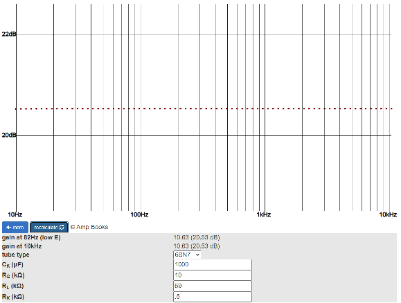
... and below is the same frequency curve except with a cathode bypass cap of 1000uF

1635368897872.png

You can see that the frequency curve gets slightly flatter each time until with a cathode bypass value of 1000uF it is extremely flat and linear at all frequencies from 10Hz to 10kHz! The 10Hz doesn't really matter because it is way below human hearing, and certainly mine...

Looks like in all cases the frequency curve is pretty linear at most frequencies but listening tests must have the final say which we have done with caps of up to 470uF. This doesn't mean that film caps wouldn't be better due to their linearity and response speed.

Edit: Just so you can see, below left is the frequency response using my figures except that the capacitance is 1uF instead of 470uF. You can see there is no bass response at all and the frequency response only starts to come in after you get to 100Hz and beyond.

Bottom right is the frequency response using my figures except this time the tube is a 5751. The calculator is meant for guitar amps so there is no 6SL7 option but I have been told by someone on their website that the 5751 is practically the same in response as the 5751 as they both have the same amplification factor of 70. So there is practically no difference between the 6SN7 and the 6SL7 in frequency response as you can see by comparing the last graph and the second graph above.

1635513836339.png
1635513953916.png


The straight line we see is ideal as all frequencies respond in a linear way along the line from bass to treble.
 
Last edited:
Oct 30, 2021 at 12:35 AM Post #3,960 of 4,154
Screenshot_20211030-003721.jpg

Straight line in graph is not advisable as that would not taper off below 20hz so your in now suspectable to circuit oscillations or anything outside the audible range.

Stripping one of those revealed this:

image_2021-10-26_052757.png

Those colours look like brown, black, black, black and brown to me which would make it a 100Ω resistor with 1% tolerance. And they are in the wire that goes from the PCB to the 2 * 3-pin XLR output in the rear, which is also the starting point for the wires that go to the XLR headphone output
I don't remember seeing this before, but suspect it has to do with the DC offset circuit. There needs to be a load, but I believe it is already in the board, so why these resistors?

If they are in series to the balanced outputs, a possible explanation could be output level... or to make the output impedance to be high, as the output circuit impedance is low for the headphones out.
 
Last edited:

Users who are viewing this thread

Back
Top