Little DOT MK III Mods??
May 10, 2011 at 11:40 AM Post #106 of 200


Quote:
Yeah, but the strange thing is that if a component is missing and not replaced with a wire there should be a break in the signal path = no sound (for that channel). On the photo it looks as if some of the solder joints of the resistors have been tampered with. Did you buy it second hand?

 
I bought it from David on eBay. Amp was shipped directly from China. I have never made any modifications to the circuit board myself. Many solder joints (most of them actually) do look messy.


May 16, 2011 at 11:25 AM Post #107 of 200
My board is the same version as your's sonda. And mine has just one cap too. Whereas the boad is printed for two capacitors. I'm pretty sure this is related to the power supply end of things. I was under the impression this difference between the v1.0 and v2.0 boards had to do with the 6H30PI compatibilitiy. I could be mistaken though.
 
Jun 10, 2011 at 1:58 AM Post #109 of 200
Is there any room for improvement on my adapters?

http://www.head-fi.org/forum/thread/301219/review-of-the-diy-6h6n-to-e182cc-5687-tube-adapters-bullplugs-for-ld-mkii-mkiii-headphone-amplifiers/45#post_7527150
 
Jan 30, 2012 at 9:46 PM Post #112 of 200
I've had my MK III about 5  years. I use it more as an additional preamp than a headphone amp with my home stereo and especially with a  modified " JBL On stage 400"  ipod speaker(used as a tv speaker for my cable box which does a great job considering it's small size)  . The only mod I've done is parallel a pair of .22uf Audio Cap Thetas to the Eros .22 caps and .68 Auricaps to the Wima .68 caps and it certainly helped clean up the sound and make it a bit more dynamic.
 
 
Apr 16, 2012 at 3:15 PM Post #113 of 200
Yes, and although the WIMA caps are a decent sounding cap, they were sounding just a bit grainy to me. Once I swapped the WIMAs for Auricaps & Obbligatos the treble became more controlled and cleaner.
 
As a side note, I haven't come across an answer as to whether these output caps are in series or parallel. By the circuit board tracings they look like they're in series, but I don't know for sure.


Jun 7, 2012 at 2:51 PM Post #114 of 200
Mods done :)
 
Both of capacitors in LD III (0.22uF, 0.68uF) replaced with Russian PIO K40Y9. Signal cable from input connectors to the board replaced with silver one. Sounds very detailed now. Soundstage much bigger. Highs appears and they are clear. Now I need to think is it to bright or not. 
 
Anyway has anybody replaced resistors for better one? Specially on REV2 board which I have. It wood be lovely to post some photo of rev2 board with marked resistor ind capacitors on signal path.
 
Matt
 
Apr 20, 2013 at 6:19 PM Post #115 of 200
Will share my mods on my LD mk III.
 
First of all, one of my goals was not to change the external aspect of the LD mk III with cables running in and out and or external caps or components.  The LD mkIII internally have aprox 3.5cm height with aprox. 2.3cm over board space height to accomodate components and aprox 1cm available for extra components on the reverse side of the circuit board.  This is a pretty restrictive size to make mods, but finally succeeded.
 
I focused on the main problems (from my point of wiew and stricly IMHO) that are the input and output caps.
 
My Litte Dot arrived on 2013 and doesnt came with any WIMA cap.  The input cap was a Polyester one ("3,3k N5 MMK 50" printed on it) don't know the brand (maybe kemet or Rifa).  The output cap is a 220 uF electrolytic (high temperature and high expected life) bypassed with a cheap polyester metallized film cap (chinese CL21 "CL21 684J 250V" printed on it).
 
So, first of all I wanted to replace this caps, taking care of the size in order to fit them into the enclosure without problems.
 
I selected WIMA MKP Polypropylene caps (the other option for me were obbligatos but the size was some how a trouble and wanted the shortest leads as possible to reduce inductance at high frequencies).  Also selected another bypass capacitor, the well known Vishay MKP 1837, to bypass the WIMAS.  I used this combo in the past and for me is a winner.
 
The short lead problem (on board through hole designed) of the WIMA's was succesfully solved using uninsulated 24-26 AWG butt splice connectors from farnell (crimped and also with a little soldering "drop" in the open middle of the connector).
 
Finally the Mods:
Input cap:  WIMA MKP10 3.3uF 250V bypassed with Vishay 1837 0.068uF 150V
Output cap: same stock electrolytic cap bypassed with two other caps both in paralell, one WIMA MKP4 0.68uF 250V + Vishay 1837 0.1uF 150V.
220uF/16V capacitor of the driver tube substituted with Rubycon 220uF/35V ZLJ series (105°C - 10000 hours).
 
The WIMAS were fitted in the main side of the circuit board and the Vishay on the reverse side (Vishay's are very little).
 
In the future plan to change the 100K Alps 16 (16mm diameter) with a 100K stepped pot (21mm diameter), my initial physical measurements says that will fit well (the pot is fixed on the aluminium front panel but is very close to the circuit board edge and pot diameter space available is very restricted).
 
If I can find some very good aluminium electrolytic pencil shaped (max 2.1mm diameter) 220uF/250V like Jensen, maybe will try to substitute as well in the future.
 
Initial impressions:
From the very beggining and after some burn in time 20-40 Hrs I have to say that the highs are much clearer and the grainy sound heard in some recordings almost dissapeared.
 
My conclussion is that this mod results in a worth while work.
 
Will try to post some pictures, but I'm new to this forum and maybe this feature is not enabled to me now, but soon...
 
Apr 20, 2013 at 6:44 PM Post #116 of 200
Have to say that all the internal components on board in the Little Dot MK III are 85°C or 105°C long life ones, but never measured more than 45°C with my tester in the hottest point of the external enclosure side (very close to the tubes), even after  hours of use.
Tubes generates heat but they can dissipate directy to the surrounding air and I can't find any overheat problems that can shorten the expected life of the components, even assuming that internally there is more temperature (of course) that exernally (I assume that after hours of use the temperature gradient internal-external should be little, no more than 5 degrees).
 
May 1, 2013 at 10:28 PM Post #117 of 200
After some hours of listening I found that Vishays 1837 get too much brilliant in the highs and are a not good by-pass cap for electronic signals (maybe if used at very little values of capacitance this trouble will improve).
I like clear and open highs (not birilliant) and tried another by-pass combinations with cheap (non-boutique) caps.
Found that the best for me is the following:
Input cap: WIMA MKP10 3.3 uF  bypassed with Obbligato Gold 0.047 uF
Bypass for the output electrolytic stock cap:  Obbligato gold 0.68 uF
After 50+ hours of listening this combo shows clear mids and highs that makes the sennheiser HD650 sound really magnificent.
 
Jun 6, 2013 at 3:19 AM Post #118 of 200
Here's a question for folks interested in modifying their LD III amps:
 
Decades ago my uncle owned the biggest tv/radio sales and repair shop in town. He insisted that tube equipment needed a separate stepped "on" switch arrangement for the filament supplies. He claimed it would extend tube and equipment lifespan vs. an "on" switch that gave an audible thump.
 
Should tube amps have a two-stage on switch? Or is this out there in the land of hand-loomed at midnight by virgins gold wiring harnesses?
 
Thanks
 
 
FWIW, I wish the amp had a deep red or amber "on" LED. The blue is almost painful at night. A volume control with arbitrary markings from 1-11 would be a nice touch too.
 
Jun 12, 2013 at 3:17 AM Post #119 of 200
Owning the LD MKIV for several years now as well as other tube headphone amps I have never experienced an audible thump while powering up any of these
smile.gif
.
Guess it's because a headphone amp doesn't draw as much power as a speaker amp. However I'm sure that a separate switch arrangement for the filament wouldn't hurt. But how or where would you find the space to put it? The stupid little shoebox doesn't leave much room for improvement.
 
Concerning the dreadful blue LED I swapped it with a red LED because the blue one was driving me crazy. Be aware that LEDs come with different light intensity. The red one I bought is quite dimmed. For some reason all chinese equipment come with blue LEDs. Makes it easier to tell them apart though :)
 
Disclaimer: Mind you I have limited knowledge about electrical design. I'm just talking from experience. (just one tiny shock hazard so forth).
 
 
Aug 1, 2013 at 8:11 AM Post #120 of 200
Problem with the MKIII I had is a faulty volume pot, I think. Read below to see the whole story and say if you think the volume pot is a problem too.
 
For a short version of the question... which volume pot should or can I buy?  Should I just get the same Alps 16 100KAX2 as stock, or is it worth while to upgrade to a better pot?
 
 
Now, for the problem:
 
I bought a used MKIII. Worked fine for a few hours, then left channel stopped working completely. Right channel worked fine. White RCA input signal didn't reach the headphones, but input going trough the red RCA did work.  So I tried replacing tubes, different power cable, different RCA cable, source, fuse, etc. Nothing changed, always right channel worked, left didn't. 
 
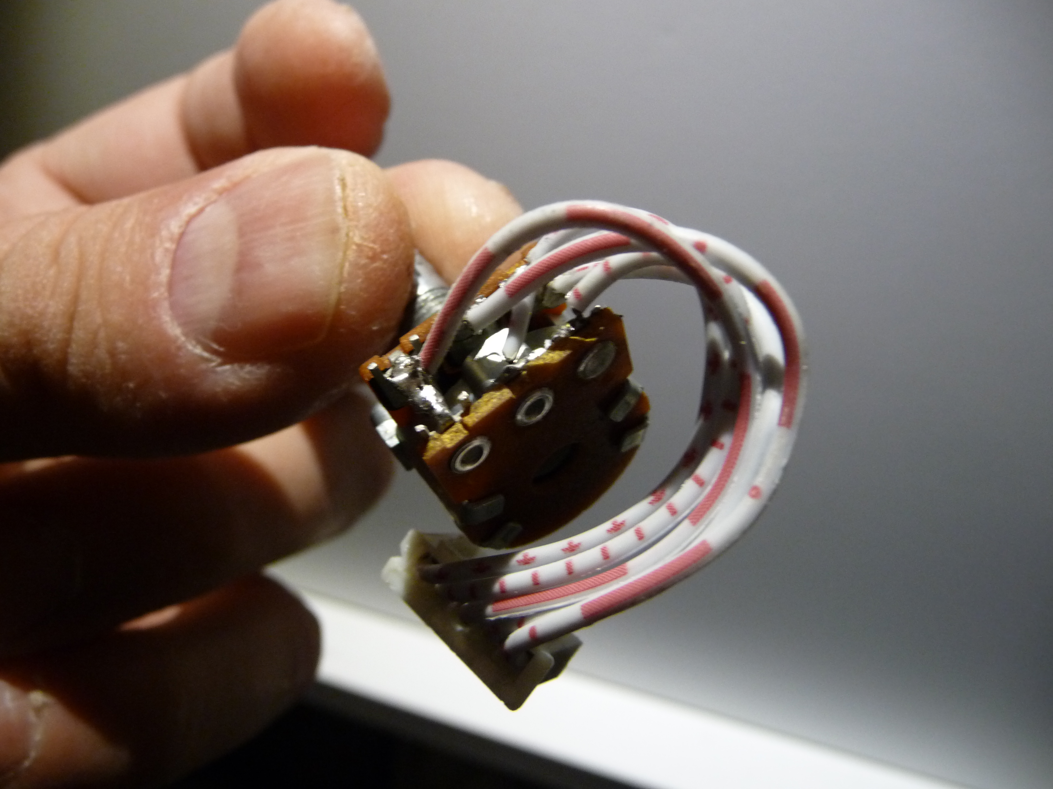
So I opened up the amp and saw some cables fell off of the volume pot. While trying to get the volume pot off, I ripped off the rest of the cables.  Now I soldered them again, in the same order as they were before and as they should be soldered, and now the LEFT channel works, but the RIGHT one doesn't.  And its not the case of me soldering wrong channels, because now the WHITE rca input works, but the RED rca doesn't, so its the opposite to before.  My guess is the reason for that is my poor soldering, because it really is poor.
 
Also, the volume pot sometimes seems smooth when turning, but sometimes its rough. Like there are spots that are rough, and not always on the same place, like there's something inside the volume pot moving around and screwing with the signal. I guess I'll just have to replace it.
 

Users who are viewing this thread

Back
Top