Little DOT MK III Mods??
Apr 29, 2011 at 2:35 AM Post #91 of 200
Stevebol,
 
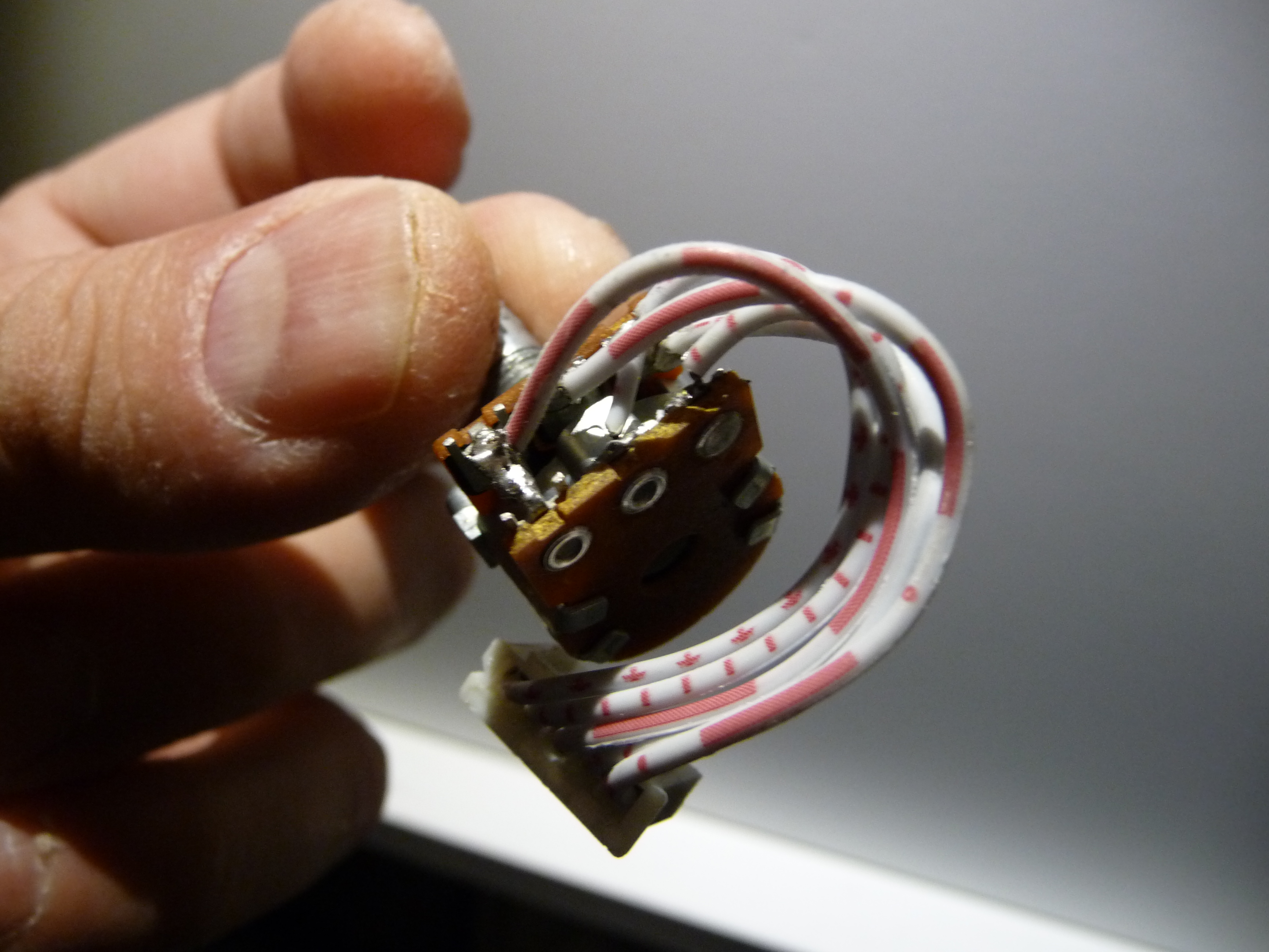
Looks like the soldering quality is very poor not only on my MKIII. My clumsiness did not help either I guess :wink: I think I figured out the pot wiring. It works fine... sometimes... well... I loose the left channel when I touch the pot in an improper manner :wink: I had some problems with the pot before and I assume it got damaged during the process of rewiring. I’ll check my soldering job later but I’m quite confident I did a decent job with my soldering iron.
 
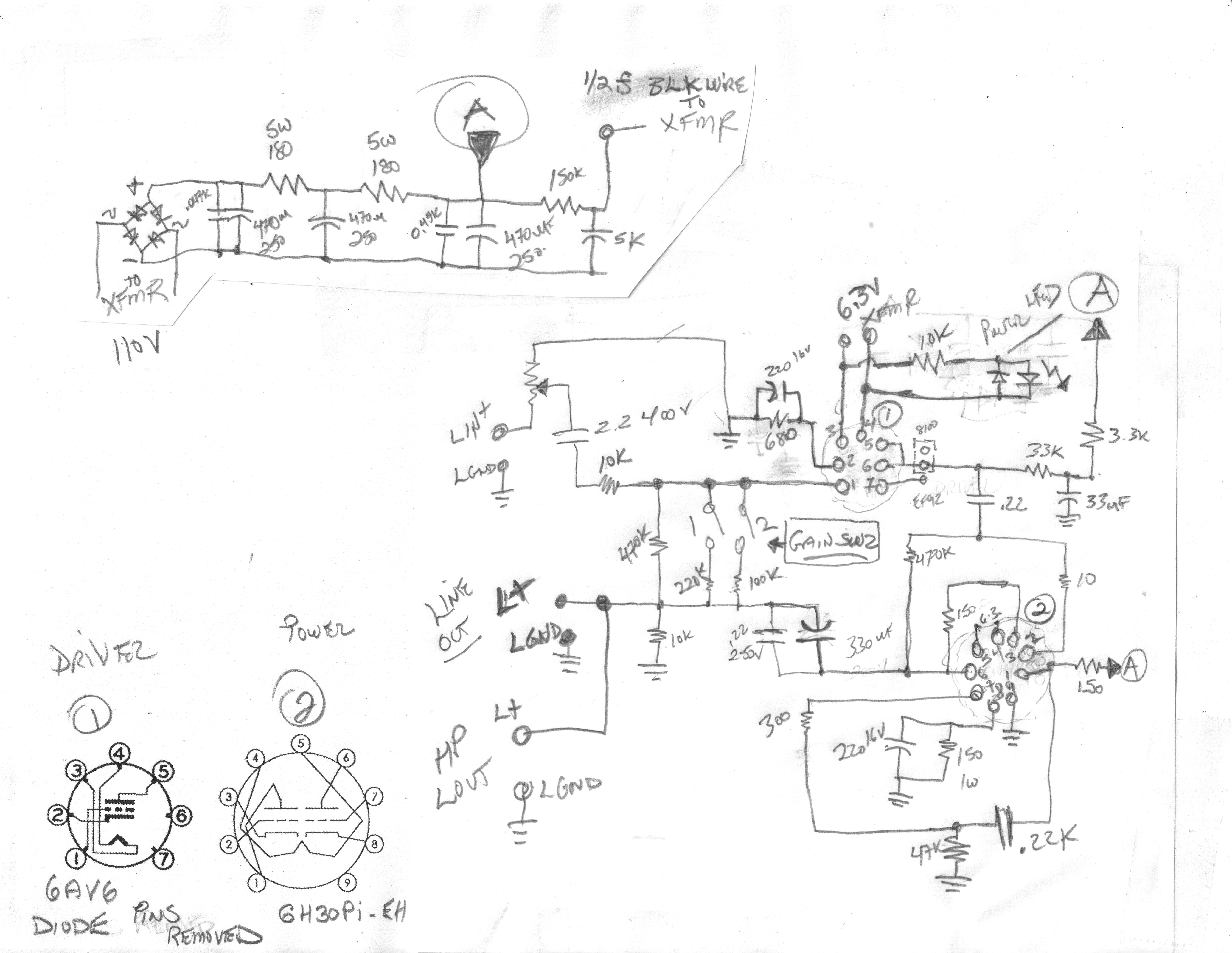
Here is a key/legend for the rough sketch I did:
O – orange
WO – white orange
B – brown
WG – white green
G - green
 
Bear in mind I have never consulted the wiring with anyone and it is my educated guess only. Do not attempt this at home unless you are entirely sure and confident bla bla bla... :wink:
 
 
http://img848.imageshack.us/img848/8601/copyofdsc05647.jpg
 
http://img405.imageshack.us/img405/7887/copyofdsc05652.jpg
 
http://img641.imageshack.us/img641/3722/copyofdsc05763.jpg


Apr 29, 2011 at 6:12 PM Post #92 of 200
Your wiring looks correct. On my version of the MKIII there is a five pin socket soldered to the circuit board. The pot then plugs into the surface socket with a five pin harness being wired from the pot. Also different is my wire colors: red, blue, brown, green and black.
 
But I believe the outside green and orange wires on yours, which solder to the circuit board, do output to the pot. And the inside striped wires are inputs from the pot. And the common ground is or course the circuit board's center soldering point. Although the circuit board has the L and R printed to distinguish between left/right channel soldering points, there's no indication for the in & out from the pot.
 
A while back I sent my MKIII for a short fall while I had the face plate detached which pulled the wiring from the pot. 
redface.gif
 I ended up using a heavier gauge wire because those that were the original wires were much too fragile, being much too light a gauge for my liking.
 
May 2, 2011 at 1:45 PM Post #95 of 200
I have. I swapped out the 3.3uf and 0.68uf WIMA's for equivalent Auricap's and Obbliggato's respectively. Both caps fit nicely, with thin foam packing, into the side bulges of the case. As well, I swapped the 220uf Nippon Chemicon, which were on the output side, for some equivalent, but higher voltage, Nichicon's. Since I'd torn the original Alps pot from the wiring I decided to also swap that pot out for an Alps 947G, which is physically larger. Now I have to extend the front plate out with a block of wood. Unfortunately I'm dealing with seepage flooding in my shop (ah... spring-time) otherwise I'd have fashioned a new mount for it by now.
 
On the power wiring side, I replaced the wires and am going to route the power wires out the rear of the transformer housing and down into the top-rear of the case. I disliked the way the wires were originally routed through the floor of the transformer housing and into the top of the case, with no grommets to protect the wires from the sharp machined edges. I''m going to employ grommets and a split wire loom in my rerouting to tidy it all up.
 
In terms of the capacitor swapping, I found that I've improved the clarity of the treble frequencies. Doesn't sound quite as harsh in the highs now, I don't think it was really grainy before, just a bit harsh. Still has plenty of detail though. Nice match for the HD650's.
 
May 4, 2011 at 5:27 PM Post #96 of 200
Would it be possible to use 50k attenuator instead of 100k pot in my MKIII?
 
Edit:
Like the one from the link bellow:

http://cgi.ebay.com/DACT-Type-21-Stepped-Attenuator-Potentiometer-50K-300B_W0QQitemZ120473999989QQcategoryZ3280QQcmdZViewItemQQ_trksidZp4340.m263QQ_trkparmsZalgo%3DSIC%26its%3DI%252BC%26itu%3DUCI%252BIA%252BUA%252BFICS%252BUFI%26otn%3D10%26ps%3D63
 
They seem to be identical size wise. I’m asking specifically about 50k because if it is not drop-in replacement I might use it in another project later on.
 
May 5, 2011 at 9:52 PM Post #97 of 200
The pot you're looking at is a "stepped attenuator" pot. Besides meaning incrimental volume changes, as opposed to gradual, they're suppose to offer other benefits in sound quality. But someone else will have to give you advice on this as I know not how stepped pots work. I don't think there is any problem using a lower impedance pot though, other than greater volume.
 
May 6, 2011 at 4:06 PM Post #98 of 200
I took some pictures of the circuit board of my MKIII v2.0 today and I think (pardon my ignorance) there is something missing on the board. There is one brown 33uF 250V cap in the middle of the board. Looks like there should be two of them. There is nothing on the other side of the board. There is nothing rattling in the housing either :wink: Am I missing something? Can anyone confirm there should be only one cap there?
 
And if you could take a look at the components of my MKIII and suggest some element swapping to upgrade the SQ? Preferably something cheap and easily obtainable on eBay.Thanks :)


Sorry for the crooked picture. It’s actually made of 2 different photos. I couldn’t pull the board out far enough to take one nice shot.
 
 
May 8, 2011 at 5:50 PM Post #99 of 200
[size=11pt]Today I visited my local shop with electronic stuff. There is nothing I mean absolutely nothing in terms of caps or resistors mentioned in the LD mod thread :frowning2: The only things I could scavenge were some LEDs. From top to bottom:
- original blue
- orange
- superbright white
- superbright orange[/size]


[size=11pt]I think I’ll stick to the superbright orange.[/size]
 
[size=11pt]Can anyone help me with Ebay suggestions?[/size]
 
May 9, 2011 at 3:15 AM Post #100 of 200
Hey Sonda, thanks for the pics. It should be a big help and I'm going to get started trying to put my LD back together. I haven't decided on the enclosure yet but I'll probably go with a simple wood box and put the transformer and tubes on top.
 
May 9, 2011 at 5:48 AM Post #101 of 200


Quote:
I took some pictures of the circuit board of my MKIII v2.0 today and I think (pardon my ignorance) there is something missing on the board. There is one brown 33uF 250V cap in the middle of the board. Looks like there should be two of them. There is nothing on the other side of the board. There is nothing rattling in the housing either :wink: Am I missing something? Can anyone confirm there should be only one cap there?
 
And if you could take a look at the components of my MKIII and suggest some element swapping to upgrade the SQ? Preferably something cheap and easily obtainable on eBay.Thanks :)


Sorry for the crooked picture. It’s actually made of 2 different photos. I couldn’t pull the board out far enough to take one nice shot.


Concerning the 'missing' brown capacitor you could check the board to see if there are two empty soldering holes. (Probably close to the existing capacitor). Every component in the design should have a small text printed just next to where it's placed in the design (like '100K' for a resistor or '33uF 250V' for a capacitor). So if there is only one text with the '33uF 250V' printed you shouldn't worry.
 
Here you can see the LD MKIII board but it's the vers. 1 so it's not much help as there can be significant changes in the design:
http://www.littledot.net/forum/viewtopic.php?f=9&t=815&sid=ae7df9704ce470031d3523cbaf8f435d
 
Of course you can always drop David a line for help. He's usually quick with an answer.
 
May 10, 2011 at 1:48 AM Post #103 of 200
Looks like all you need to do is to stand up the existing 33/250, and then decide if it's supposed to have another one in the unoccupied space.
 
I'd check with David at Little Dot on this. He usually responds quickly.
 
May 10, 2011 at 11:22 AM Post #104 of 200
Yeah, but the strange thing is that if a component is missing and not replaced with a wire there should be a break in the signal path = no sound (for that channel). On the photo it looks as if some of the solder joints of the resistors have been tampered with. Did you buy it second hand?
 

Users who are viewing this thread

Back
Top