


DBaldock9
Headphoneus Supremus
Great idea and well implemented!
Thanks!
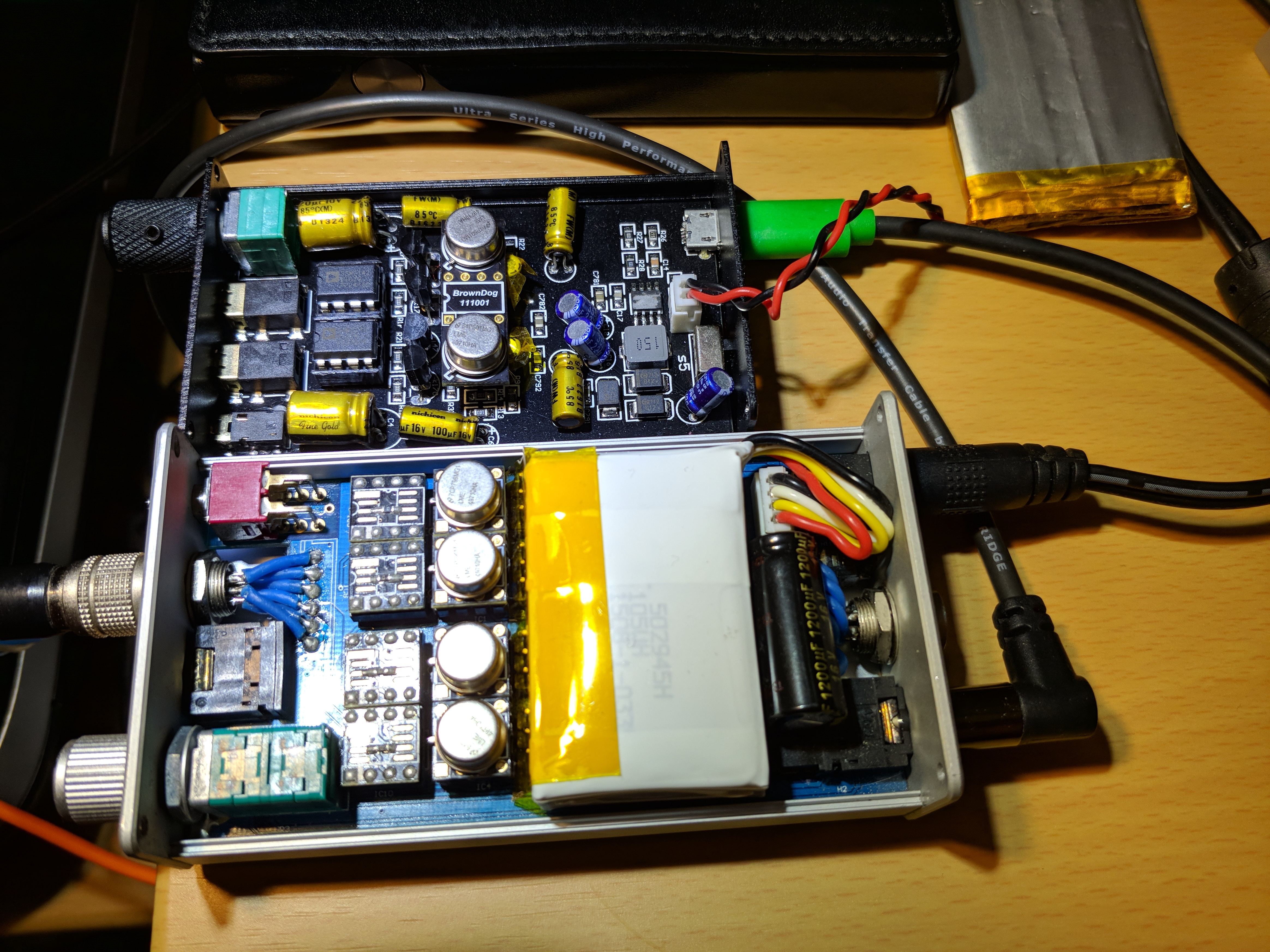
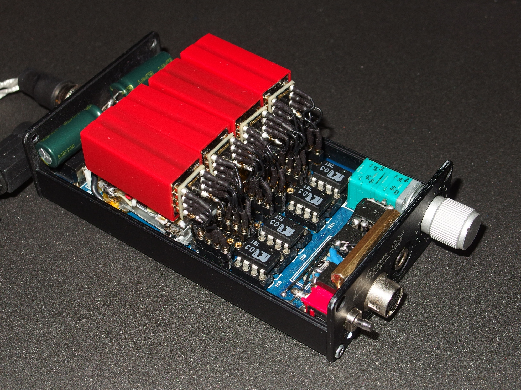
I used 18 gauge solid copper wire, so it was a bit tricky getting them routed to the correct lugs.
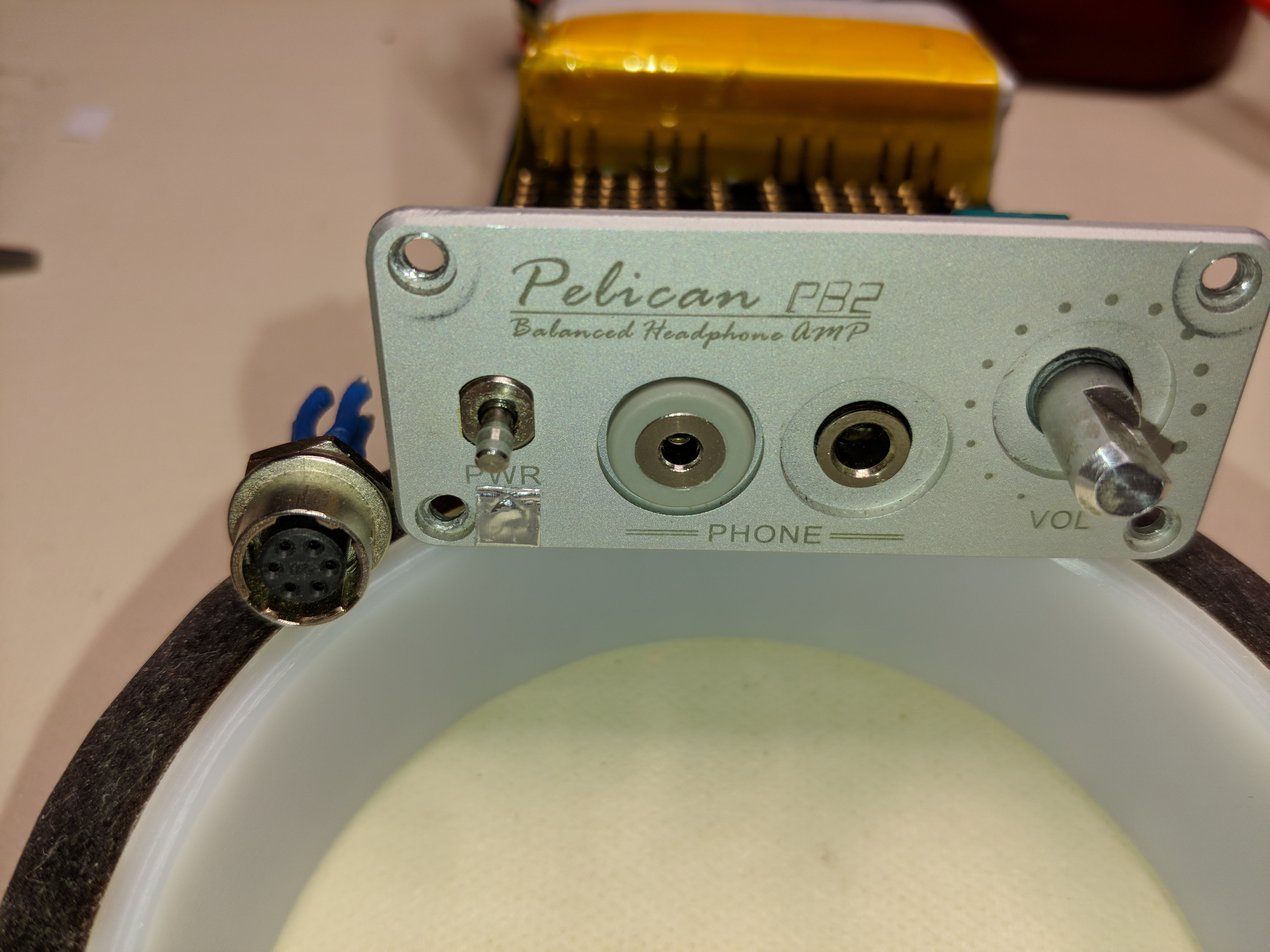
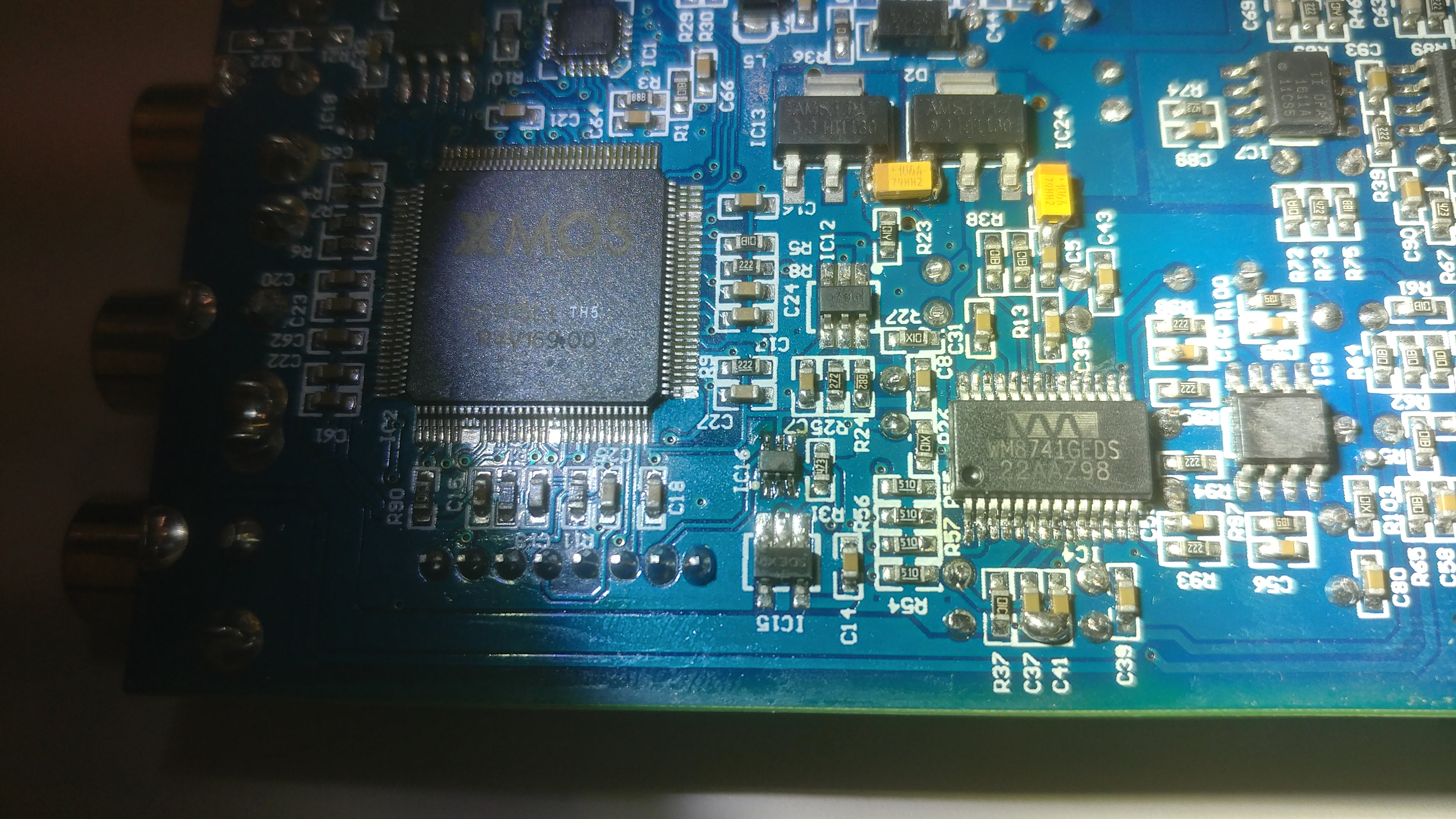
Looking back through this thread, you'll see where the pin-out for the original Hirose 6-pin connector is shown.
So, that allowed me to determine which circuit board pads are which signals.
I used Kapton tape over the two pads (#1 & #4), for Right & Left channel GND, since the earphones only need the (L+), (L-), (R+), & (R-) signals.
Since it's deeper than the Hirose jack, the back edge of the 2.5mm jack did require some filing, so that it would clear the circuit board.
") Love warm sound :3 And darkest too! Have you tried role db2 opamp? With blue it sounds wider and YAMY :3 Whats opamp in your db2? Thank you for the fast replay!
Love warm sound :3 And darkest too! Have you tried role db2 opamp? With blue it sounds wider and YAMY :3 Whats opamp in your db2? Thank you for the fast replay!